
thermometer circuit using lm335

The LM335 is a precision temperature sensor that operates over a wide temperature range, typically from -40 degrees Celsius to 100 degrees Celsius. It is a three-terminal device that outputs a linear voltage proportional to the temperature in degrees Celsius. The sensor's output is directly related to the temperature, allowing for straightforward conversion to a digital readout using a multimeter or an analog display.
The adjustment circuitry is crucial for calibrating the output voltage to ensure accurate temperature readings. This may include operational amplifiers configured as voltage followers to buffer the output signal, as well as resistive voltage dividers to set the reference voltage accurately. The reference voltage is essential for establishing a baseline measurement, ensuring that the output from the LM335 can be interpreted correctly.
For practical applications, the circuit can be implemented on a printed circuit board (PCB) for enhanced stability and durability. Additionally, it is advisable to use high-precision resistors in the adjustment circuitry to minimize errors and enhance the accuracy of the temperature readings. The circuit can be powered using a standard DC power supply, ensuring that the LM335 operates within its specified voltage range for optimal performance.
In summary, this thermometer circuit utilizing the LM335 sensor provides a reliable method for temperature measurement, with the ability to easily interface with digital voltmeters for straightforward reading and calibration. The design emphasizes accuracy and simplicity, making it suitable for various temperature sensing applications.This circuit in below is show the simple form of the thermometer circuit. The circuit is based on LM335 as sensing the temperature. This is the figure of the circuit. The circuit consists of two parts: The LM335 and its adjustment. The output of the LM335 is 10 millivolts per degree C, with 25 degrees C corresponding to 2. 982 VDC. A reference circ uit provides a zero reference voltage. It is adjusted to (2. 982 volts - (25 degrees x 10 milli volts/degree) = 2. 832 volts. To read the temperature of the LM335 directly in degrees C, connect the + lead from a high impedance DVM to the output pin and the end of the DVM to the 2. 732 volt pin. The factor of 10 milli volts per degree C is equivalent to 10 milli volts per degree K, since a change of one degree C is equal to a change of one degree K.
The difference in the two scales is only their offsets. The melting point of water ice is 0 degrees C and 273. 15 degrees K. The boiling point of water is 100 degrees C and 373. 15 degrees K. 🔗 External reference
Related Circuits
The circuit was quickly assembled from components available in a home lab and performed well during initial tests using a telephone line simulator and a line connected to a PBX. Reports indicate that this circuit functions effectively in Australia....
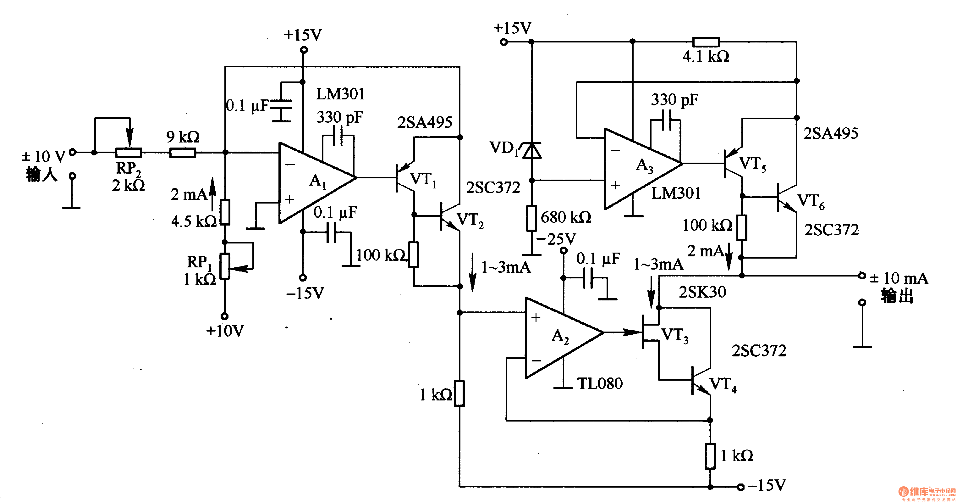
This circuit is designed for voltage-to-current conversion, specifically transforming a ±10V input voltage into a ±1mA output current. The conversion process is facilitated by operational amplifier A1 and transistors VT1 and VT2, which are responsible for altering the current...
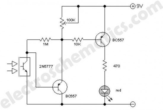
This enhanced infrared detector is designed for use with commercial infrared remote control handsets. This compact circuit is effective for quick go/no-go applications. The infrared detector circuit is engineered to respond to signals emitted by infrared remote control devices, commonly...
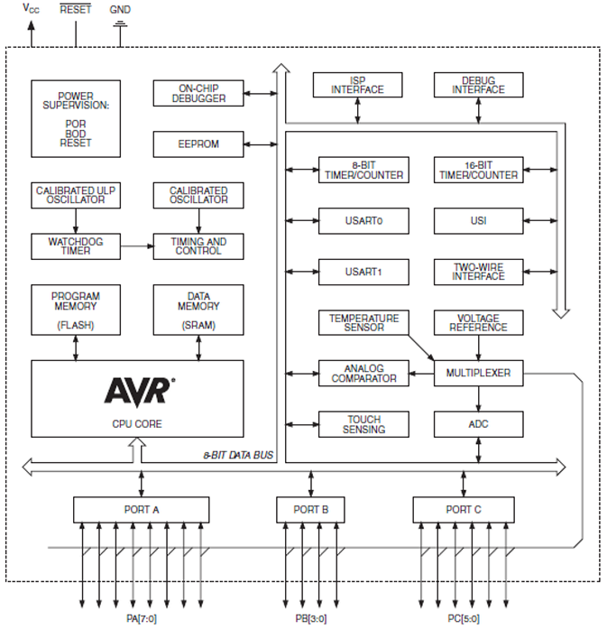
The ATtiny1634 8-Bit AVR Microcontroller from Atmel is based on the enhanced RISC architecture of AVR. It can execute powerful instructions in a single clock cycle, achieving throughputs close to 1 MIPS per MHz. This allows system designers to...
A new user has joined the forum and is seeking assistance with circuit design. They express a desire for guidance and acknowledge their inexperience in the subject. In circuit design, it is crucial to understand the fundamental components and their...
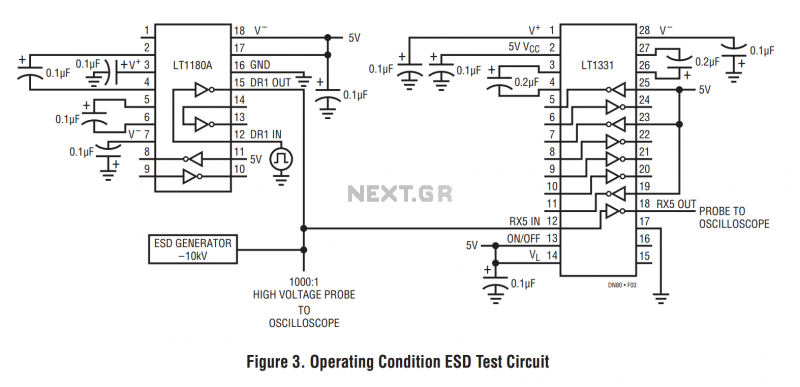
The machine model, commonly used for ESD testing in Japan, is a more severe ESD test. This model simulates metallic contact between the device under test and a charged body. The source capacitor is 200pF with no limiting resistor....