
60W Linear amplifiers

The 60 Watt linear amplifier circuit is designed for efficient amplification of RF signals, leveraging the capabilities of the IRF840 MOSFET. This device is characterized by its high power output and robust thermal performance, making it suitable for various applications in amateur radio and RF transmission.
The amplifier's configuration allows for a maximum output power of 60 Watts while drawing a current of 700 mA at 60 Volts. The choice of the IRF840 is strategic, as its maximum power handling capability of 125 Watts ensures reliable performance under typical operating conditions. The circuit's simplicity is enhanced by the use of a single MOSFET, which simplifies alignment and troubleshooting.
To prevent thermal overload, it is imperative to use an adequate heat sink to dissipate heat generated during operation. The alignment procedure involves connecting a dummy load, such as a small bulb, which serves as a safe testing method to monitor the output without risking damage to the amplifier. The use of a 10K preset resistor allows for fine-tuning of the drain current, targeting approximately 100 mA for optimal performance.
The gate voltage is a critical parameter that must be managed carefully. Operating the gate voltage at 0.8V minimizes the risk of self-oscillation, a phenomenon that can lead to catastrophic failure of the MOSFET. The design specifies a maximum gate voltage of 2V, with 1V being the recommended operating point to ensure reliability.
The output stage includes a coil wound on the drain of the IRF840, consisting of 3 turns of 20 SWG wire on a balun core formed by stacking two T13.9 toroids. This configuration aids in impedance matching and enhances the amplifier's performance. Additionally, the RFC (Radio Frequency Choke) on the Vcc line is constructed from 20 turns of 20 SWG wire on a T20 toroid, which helps in filtering out unwanted RF signals and stabilizing the power supply.
Overall, this linear amplifier circuit exemplifies a well-thought-out design that balances performance, simplicity, and reliability, making it an excellent choice for amateur radio enthusiasts and RF applications.The 60 Watt linear amplifier is simple all solid state circuit using power mosfet IRF840. The IRF series of power transistors are available in various voltage and power ratings. A single IRF840 can handle maximum power output of 125 watts. Since these transistors are used in inverters and smps they are easily available for around Rs: 20/-. The IRF linear amplifier can be connected to the out put of popular VWN-QRP to get an output of 60 Watts. The circuit draws 700 ma at 60 Volt Vcc. Good heat sink is a must for the power transistor. Alignment of the circuit is very easy. Connect a dummy load to the out put of the circuit. You can use some small bulb like 24V 6Watts as the dummy load. I have even used 230V 60Watts bulb as dummy load with my IRF840 power amplifier working at 120Volts. Adjust the 10K preset to get around 100 ma Drain current. I used gate voltage of 0. 8V with my linear amplifier. A heigh gate voltage can make the power transistor get distroyed by self oscillation. So gate voltage must be below 2V and fixing at 1V will be safe. The coil on the drain of IRF is 3 turns 20 SWG wound on 4 number of T13. 9 torroids (two torroids are stacked to form a balun core). The RFC at the Vcc line is 20 Turns 20 SWG wound on T20 torroid. 🔗 External reference
Related Circuits
The National Semiconductor LMV225 is a linear RF power meter integrated circuit (IC) housed in a surface-mount device (SMD) package. It operates within a frequency range of 450 MHz to 2000 MHz and requires only four external components for...
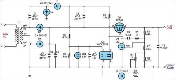
This circuit is a MOSFET-based linear voltage regulator with a voltage drop as low as 60mV at 1A. It utilizes a 15V-0-15V transformer and an IRF540 N-channel MOSFET (Q1) to deliver a regulated 12V output. The required gate drive...
The Wien-Bridge oscillator meets specific requirements due to the presence of a low-pass filter, a high-pass filter, and a 180-degree phase shift from the feedback networks connecting the input to the output. This configuration results in a total phase...
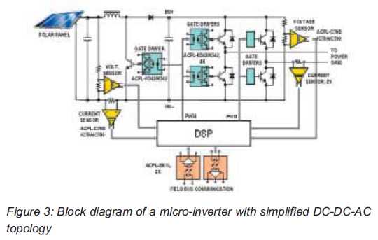
Both help improve efficiency and protect micro-inverters in photovoltaic (PV) solar applications. In 2009, the residential solar photovoltaic (PV) inverter market represented 90 percent of the total PV. The integration of micro-inverters in photovoltaic solar applications has significantly enhanced system...
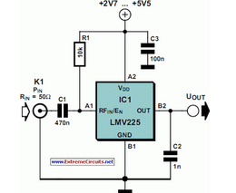
The National Semiconductor LMV225 is a linear RF power meter integrated circuit (IC) in a surface-mount device (SMD) package. It operates over a frequency range of 450 MHz to 2000 MHz. The LMV225 is designed for precise measurement of radio...
Since I have provided the schematic for John L Linsley-Hood's Class-A amplifier, I felt that some readers may wish to experiment with the concept. Unfortunately, a very low ripple power supply is needed for all Class-A amps, and the...