
6M 100W Linear Amplifier
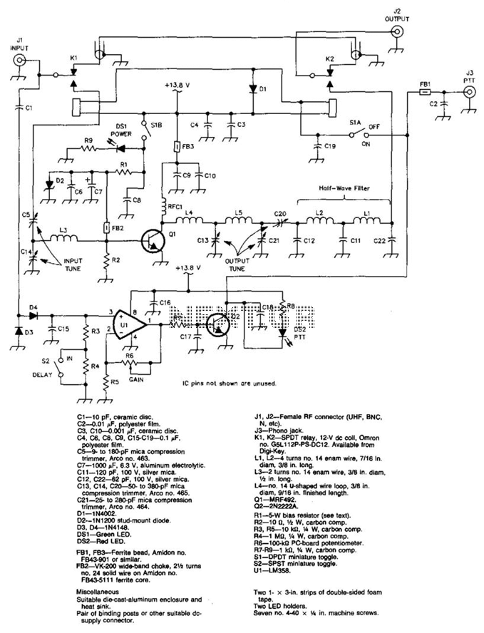
This circuit is designed to deliver a 100 W output at a frequency of 50 MHz, making it suitable for high-frequency RF applications. The core functionality revolves around U1 and Q2, which act as a T-R (transmit-receive) relay driver. This configuration allows the amplifier to switch on automatically when an RF signal is detected at the input connector J1. During the receive mode, the circuit ensures a direct connection between J1 and J2, facilitating seamless signal flow without the need for additional processing.
The power supply for the amplifier is specified at 13.8 V, which is standard for many RF applications. The circuit employs a variety of capacitors to manage frequency response and stability. Capacitors C1 through C10 serve different roles, including filtering and tuning, with values ranging from 10 pF ceramic discs to 1000 pF aluminum electrolytic capacitors. The use of mica compression trimmers (C5, C13, C14, C20, C21) allows for fine-tuning of the circuit parameters, which is critical in RF applications where precision is essential.
The diode selection includes standard rectifier diodes (D1, D2) and signal diodes (D3, D4) that provide necessary protection and signal integrity. The inclusion of LEDs (DS1, DS2) indicates the operational status of the circuit, with a green LED for power and a red LED for fault indication.
Ferrite beads (FB1, FB3) and a wide-band choke (FB2) are used for RF noise suppression, ensuring that the amplifier operates efficiently without unwanted interference. Connectors J1 and J2 provide flexibility in RF connectivity, accommodating various RF connector types such as UHF, BNC, or N connectors, while J3 serves as an auxiliary phono jack.
Relay components (K1, K2) are specified for the switching mechanism, utilizing a 12 V DC coil relay, which is a common choice for RF switching applications. The inductors L1 through L4 are wound with no. 14 enamel wire, providing the necessary inductance for RF signal processing.
Resistors R1 through R9 are used for biasing and signal conditioning, with values carefully chosen to ensure proper operation of the circuit. The inclusion of a potentiometer (R6) allows for adjustable gain, enhancing the circuit's versatility.
The overall assembly of the circuit is designed for durability and efficiency, utilizing a die-cast aluminum enclosure and heat sink to manage thermal output effectively. Additional components such as binding posts and machine screws facilitate easy assembly and integration into various setups. This circuit is a robust solution for applications requiring high-power RF amplification with reliable performance. 100 W output at 50 MHz is available from this circuit. Ul and Q2 form a T-R relay driver, switching the amplifie r on when RF input at J1 is sensed. During receive periods, J1 and J2 are directly connected. A 13.8-V supply is required for this amplifier. C1—10 pF, ceramic disc. C2—0.01 polyester film. C3, C10—0.001, ceramic disc. C4, 06, C8, C9, C15-C19—0.1 . polyester film. C5—9- to 180-pF mica compression trimmer, Arco no. 463. c7—1000 pF, 6.3 V, aluminum electrolytic. Oil—120 pF, 100 V, silver mica. C12, C22—62 pF, 100 V, silver mica. C13, C14, C20—50- to 380-pF mica compression trimmer, Arco no. 465. C21-25- to 280-pF mica compression trimmer, Arco no. 464. D1—1N4002. D2—1N1200 stud-mount diode. D3, D4—1N414B. DS1— Green LEO. DS2—Red LED. FB1, FB3—Ferrite bead, Amldon no. FB43-901 or similar. FB2—VK-200 wide-band choke, 2Vi turns no. 24 solid wire on Amidon no. FB43-5111 ferrite core. qst J1, J2—Female RF connector (UHF, BNC, N, etc). J3—Phono jack. Kl. K2—SPDT relay, 12-V dc coll, Omron no. G5L112P-PS-DC12. Available from Digi-Key. L1, L2—4 turns no. 14 enam wire, 7/16 In. diam, 3/8 in. long. L3—2 turns no. 14 enam wire, 3/8 in. diam, h. in. long. L4—no. 14 -shaped wire loop, 3/8 in. diam, 9/18 in. finished length. Q1—MRF492. Q2—2N2222A. R1—5-W bias resistor (see text). R2—10, xh W, carbon comp. R3, R5—10 KOhmhm, V* W, carbon comp. R4—1, 1/4 W, carbon comp. R6—lOO-KOhm PC-board potentiometer. R7-R9—1 kti, V!» W, carbon comp. 51—DPDTminiature toggle. 52—SPSTminiature toggle. U1— LM358. Miscellaneous Suitable die-cast-aluminum enclosure and heat sink. Pair of binding posts or other suitable dc-supply connector. Two 1- 3-ln. strips of double-sided foam tape. Two LED holders. Seven no. 4-40 "/« in. machine screws. 🔗 External reference
Related Circuits
Magnetic pickups in musical instruments exhibit a relatively high output impedance, which can lead to a decrease in treble response when connected through long cable runs or to equipment with low input impedance. This preamplifier addresses these challenges by...
This is a 25 Watt basic power amplifier designed to be relatively easy to build at a reasonable cost. It offers better performance than standard STK module amplifiers commonly found in mass-market stereo receivers. The original design was created...
The circuit features a Class AB audio amplifier integrated circuit (IC) that necessitates only a minimal number of external components. This series is straightforward to construct. The 10W stereo amplifier circuit requires a stable power supply with a voltage...

This unit is designed to connect to an existing car stereo amplifier, providing the additional "punch" often desired in music playback by driving a subwoofer. Since very low frequencies are omnidirectional, a single amplifier is needed to power this...
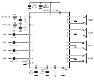
The TDA7383 features a fully complementary PNP/NPN output configuration, enabling a rail-to-rail output voltage swing without the need for bootstrap capacitors. This design significantly reduces the component count, allowing for compact assemblies. An integrated clipping detector facilitates gain compression...
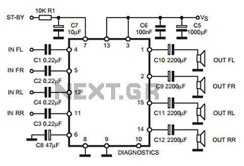
The following circuit illustrates a 35W quadruple amplifier and a 2 x 25W bridge amplifier based on the TDA7375 integrated circuit (IC). This circuit requires a minimal number of external components. Although initially designed for car applications, it can...