
Electric Guitar/Violin Preamplifier
The described preamplifier circuit is designed to enhance the performance of magnetic pickups in musical instruments by effectively managing impedance mismatches and signal integrity. The use of JFET input transistors in the TL074 op-amp configuration ensures minimal signal distortion and high input impedance, which is crucial for preserving the tonal quality of the instrument. The AC coupling at the input stage prevents DC offset issues and allows for a clean signal to be amplified.
The adjustable gain feature, facilitated by the variable resistor VR1, enables users to tailor the amplification to suit different performance environments or personal preferences. The subsequent volume control via VR2 allows for additional flexibility in managing output levels. The parallel connection of the remaining op-amps (IC1b-IC1d) not only lowers the output impedance but also enhances the output drive capability, ensuring compatibility with a wide range of audio equipment.
The inclusion of series resistors for short-circuit protection is a critical design consideration, safeguarding the op-amps from potential damage due to unexpected load conditions. The output capacitors ensure that the DC level is appropriately managed, with the resistors at the output providing a safe operating condition for the circuit. The potential for adjusting the impedance of Output 2 via VR3 adds versatility, allowing for various connection scenarios without compromising signal quality.
In conclusion, this preamplifier circuit represents a well-engineered solution for addressing common challenges faced by magnetic pickups, ensuring that musicians can achieve optimal sound quality and performance reliability.Magnetic pick-ups in musical instruments have a relatively high output impedance. This can result in a reduction in treble response when connected via a long cable run or to equipment with a low input impedance. This preamplifier provides a high input impedance and a low impedance output, solving both issues. It has adjustable voltage gain and can run off a battery or DC plugpack. The input signal is AC-coupled to the non-inverting input of IC1a, part of a TL074 quad op amp. This has JFET input transistors and the input impedance is set by a 330k © bias resistor which also sets the DC level at this input to half supply (Vcc/2). This is generated by a voltage divider comprising two 10k © resistors and bypassed by a 47 µF capacitor to reject noise and hum.
IC1a is configured as a non-inverting amplifier with a gain of between 2 and 20, depending on the setting of VR1. IC1a`s output is fed to VR2 via a 22 µF capacitor, allowing the output volume to be set. The audio then passes to the non-inverting inputs of the remaining three op amps (IC1b-IC1d) which are connected in parallel to provide a low output impedance; it will drive a load impedance as low as 600 ©.
The 100 © resistors in series with the outputs provide short-circuit protection for the op amps and also prevent large currents from flowing between the outputs in case they have slightly different offset voltages. The buffered signal is then AC-coupled to two output connectors using 47 µF electrolytic capacitors. For Output 1, a 47k © resistor sets the output DC level to ground and a 220 © series resistor provides further short-circuit protection.
Output 2 is similar but includes another potentiometer (VR3) to allow its level to be set individually. Note that this means the impedance of Output 2 can be high (up to 2. 5k © depending on the position of VR3`s wiper). The total harmonic distortion of this circuit is typically less than 0. 01% with the gain set to six. If a TL064 is used instead of a TL074, the current drain will decrease but there will be more noise at the output.
Finally, the input impedance can be increased by increasing the value of the 330k © resistor to suit high-impedance pick-ups. 🔗 External reference
Related Circuits
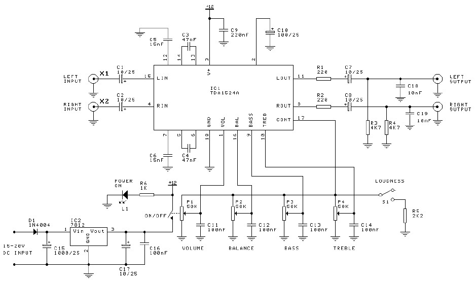
Preamplifier and tone control circuit based on the TDA1524A. The tone control circuit module is included in this preamplifier circuit, allowing for direct connection of the output channels to a stereo power audio amplifier circuit. This RIAA stereo preamplifier...
The circuit design aims to create a preamplifier for television systems that operates within the UHF frequency range of 450 MHz to 800 MHz. The preamplifier circuit is essential for enhancing weak television signals before they are processed by the...
The preamp circuit is completely conventional, and by necessity is AC coupled throughout. The artificial earth is derived by two resistors (R1 and R2), which will set the "earth" at exactly 1/2 the supply voltage. This is nominally 13.8V...
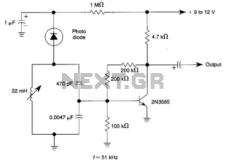
The circuit utilizes a tuned circuit for frequency selection, designed to operate at approximately 51 kHz. The 2N3565 transistor amplifies the output generated by the tuned circuit. The described circuit operates on the principle of resonance, where the tuned circuit...
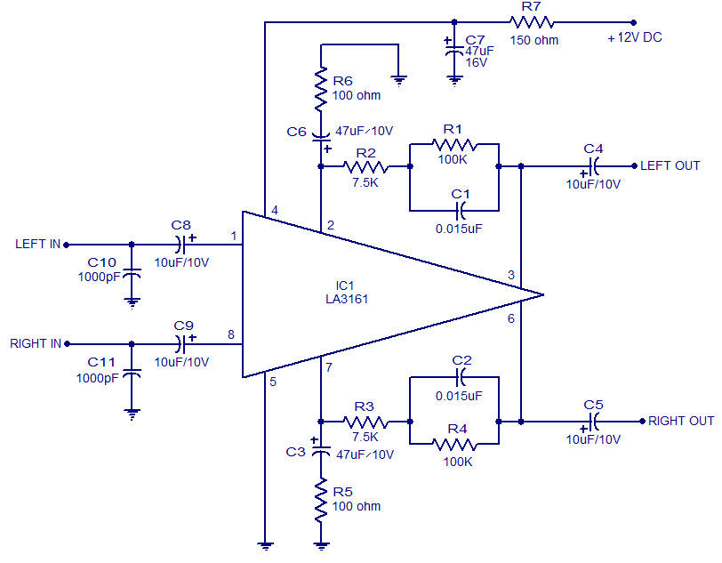
The LA3161 is an integrated two-channel preamplifier designed for car stereo applications. It operates on a 12V DC power supply. The LA3161 preamplifier is specifically engineered to enhance audio signals in automotive environments, ensuring optimal sound quality for car stereo...
Control electrical appliances using a PC. This circuit utilizes the printer port of a PC for control applications through software and some interface hardware. The interface circuit is included. The described circuit leverages the parallel printer port (also known as...
Warning: include(partials/cookie-banner.php): Failed to open stream: Permission denied in /var/www/html/nextgr/view-circuit.php on line 713
Warning: include(): Failed opening 'partials/cookie-banner.php' for inclusion (include_path='.:/usr/share/php') in /var/www/html/nextgr/view-circuit.php on line 713