
25 Watt Audio Amplifier
The 25 Watt power amplifier circuit utilizes a straightforward design that facilitates assembly and component sourcing. The core of the amplifier typically comprises a transistor-based output stage, which may include complementary push-pull configurations to enhance efficiency and reduce distortion. The input stage is designed to accommodate various audio sources, ensuring compatibility with standard consumer electronics.
The inclusion of a 10K logarithmic potentiometer allows for smooth volume control, providing a user-friendly interface for adjusting audio levels. The dual gang configuration ensures that both left and right channels in stereo applications are adjusted simultaneously, maintaining balance and sound integrity.
Grounding is a critical aspect of audio amplifier design. The recommended grounding scheme helps to mitigate potential issues related to electromagnetic interference and ground loops, which can introduce unwanted noise into the audio signal. By connecting specific components to a common ground point and ensuring that input and output grounds are isolated from the power supply ground, the design minimizes the risk of hum and enhances overall sound quality.
In terms of power supply requirements, the amplifier should be paired with a suitable transformer and rectifier circuit to provide the necessary voltage and current levels for optimal performance. The circuit design must also account for adequate heat dissipation, potentially incorporating heat sinks for the output transistors to prevent thermal overload during extended use.
Overall, this 25 Watt power amplifier represents a practical solution for audio amplification needs, combining ease of construction, cost-effectiveness, and superior performance compared to conventional amplifier modules.This is a 25 Watt basic power amp that was designed to be (relatively) easy to build at a reasonable cost. It has better performance than the standard STK module amps that are used in practically every mass market stereo receiver manufactured today.
When I originally built this thing, it was because I needed a 25 Watt PC amp and did not want to sp end any money. So I designed around parts I had in the shop. Can be directly connected to CD players, tuners and tape recorders. Simply add a 10K Log potentiometer (dual gang for stereo) and a switch to cope with the various sources you need. A correct grounding is very important to eliminate hum and ground loops. Connect to the same point the ground sides of R1, R4, R9, C3 to C8. Connect C11 to output ground. Then connect separately the input and output grounds to power supply ground. 🔗 External reference
Related Circuits
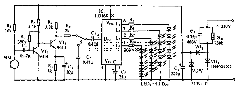
The circuit depicted in the figure involves the LD168, which functions as a sound level indicator for tape recorder speakers. It features four outputs capable of directly driving multiple light-emitting diodes. Additionally, the device can be activated by a...
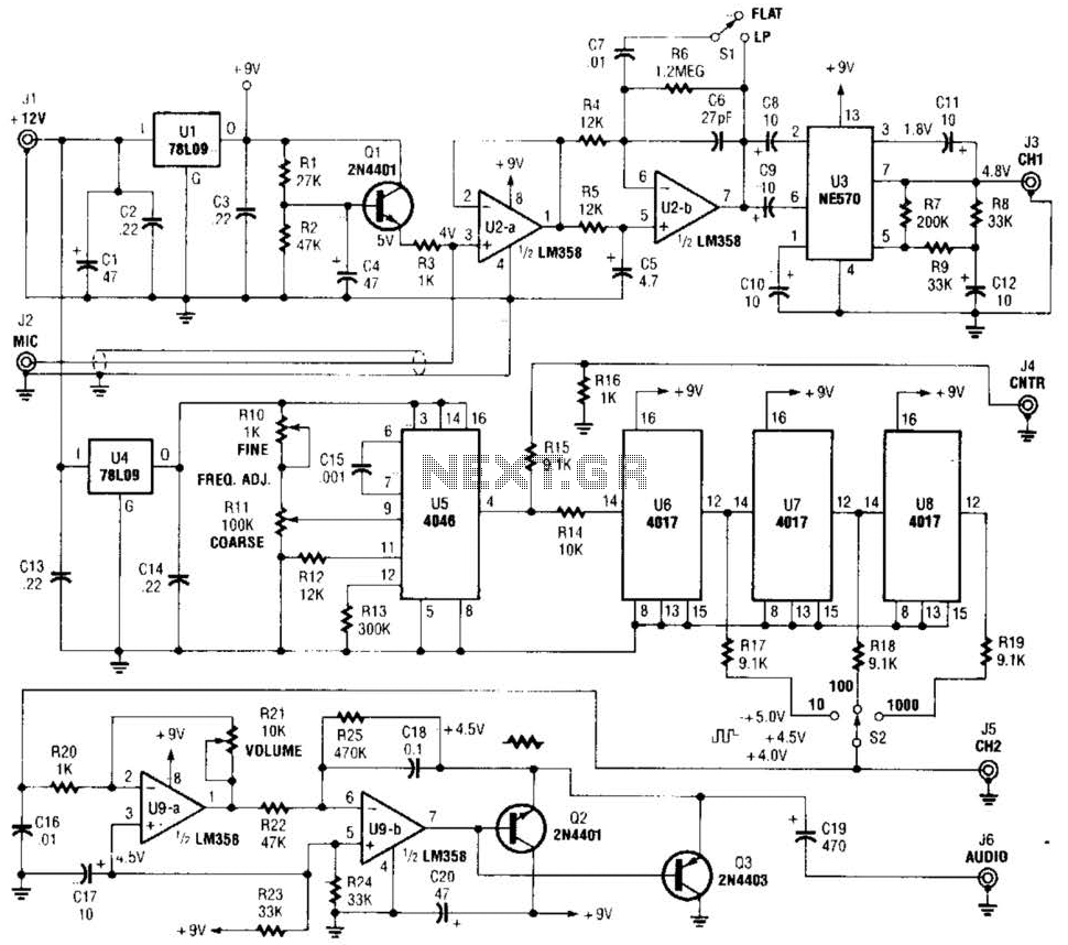
The precision audio frequency generator consists of several sub-circuits: an audio amplifier/filter circuit, an automatic level control, a variable voltage-controlled oscillator, a frequency divider circuit, an integrator, and an audio output amplifier. An electret microphone element is utilized to...
This document presents the design of an audio oscillator that operates at approximately 1 kHz. The circuit is likely sourced from EMFRD, as Wes's book contains a wealth of valuable circuits. This versatile oscillator serves as a signal source...
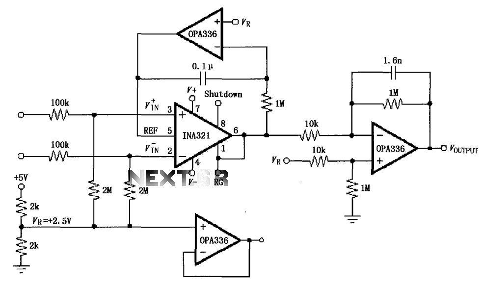
The INA321/322 forms a low-cost, medium-accuracy ECG amplifier circuit. The INA321 receives input signals from the patient's arm, amplifying them before sending the modified output to the operational amplifier OPA336. The OPA336 generates an output voltage from the inverting...
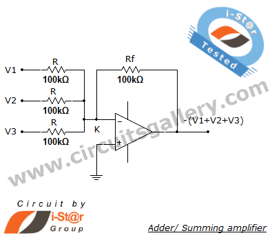
A summing amplifier, also known as an adder, is utilized to combine two or more signal voltages. This voltage adder circuit is straightforward and allows for the addition of multiple signals. It has a wide range of applications in...
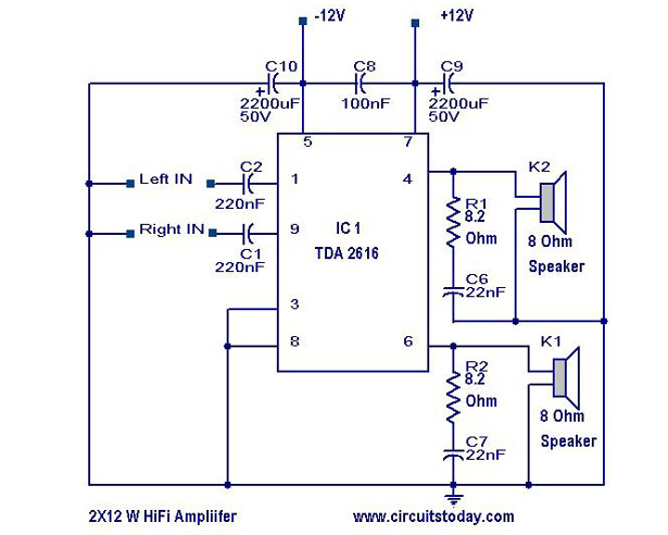
A simple Hi-Fi amplifier circuit diagram with a schematic for creating an audio amplifier design using the TDA 2616 IC. This is a stereo power amplifier suitable for radio, tape, and television applications, delivering 2 x 12 watts, totaling...