
6v to 12v converter
When the output of IC1 is at zero, the C4 charges via the diode D1 up to the power supply level minus the voltage drop at D1. When the IC1 swings to the opposite direction, its output becomes positive. The output voltage from IC1 adds up to the voltage stored at C4 forcing the diode D1 to stop conducting. C5 then charges via the diode D2 to a voltage that is double the power supply level.
The theoretical output could reach triple the supply voltage. To guard against unnecessary voltage increases at low current consumptions, a limiter stage was added to the circuit composed of a 15-volt zener diode and a Darlington transistor T1/T2. This stage caps the output voltage to about 14.2 volts. To filter out ripple from the output, C8 was also added. This helps prevent the hum signal from being noticed on radio or audio devices.
In constructing the 6 to 12 volts converter, attach the ICs to a common heatsink close to the PCB. The transistor must be attached to a separate heatsink. To get a much higher current output from the converter, C4, C5, and C6 must be increased to 2200uF.
The 6V to 12V converter circuit utilizes a TDA2003 integrated circuit (IC), which is a power amplifier designed for automotive applications, but can also function as a multivibrator in this context. The circuit operates on the principle of pulse width modulation to generate a higher output voltage from a lower input voltage. The frequency of oscillation is critical for the performance of the converter; at no load, the circuit oscillates at approximately 4 kHz, which increases to around 7 kHz under load conditions. This frequency is determined by the capacitor C3, which influences the timing characteristics of the multivibrator.
The architecture includes two operational amplifiers, IC1 and IC2. IC1 serves as the primary oscillator, while IC2 generates an inverted output signal. The interaction between these two signals facilitates the charging and discharging of capacitors C4 and C5. The charging process occurs through diodes D1 and D2, which allow current to flow in one direction only, ensuring that the capacitors store energy effectively.
The output voltage regulation is managed by a combination of a zener diode and a Darlington pair transistor (T1/T2). This regulation prevents excessive voltage output, particularly under low-load conditions, thus enhancing the reliability and safety of the circuit. Capacitor C8 acts as a filter to smooth out any ripple in the output voltage, which is particularly important in audio applications to avoid hum and noise.
Thermal management is an important consideration in the design, necessitating the use of heatsinks for both the ICs and the Darlington transistor to dissipate heat generated during operation. For applications requiring higher current output, the values of capacitors C4, C5, and C6 should be increased to 2200 µF, which will enhance the energy storage capacity and improve the overall performance of the converter. This design approach provides a cost-effective solution for converting 6V to 12V without the complexity of transformers, making it suitable for various electronic applications.This 6V to 12V converter circuit is made with an IC from SGS with several additional components. The IC is a TDA2003 but it can be replaced with a TDA2002. The cost of building the 6volts to 12 volts converter should be low enough to justify constructing it instead of modifying the entire equipment setup to work directly with a 6 volts power supply. The two principles of simplicity and functions properly without the need of the transformer. The IC1 opam functions as a stable power multivibrator. Its oscillation frequency is determined by C3. Its oscillates at around 4kHz at standby and increases in a loaded condition up to around 7kHz. The output of the IC2 opamp is identical to the IC1 oscillator signal but in the opposite phase. When the output of IC1 is at zero, the C4 charges via the diode D1 up to the power supply level minus the voltage drop at D1. When the IC1 swings to the opposite direction, its output become positive. The output voltage from IC1 adds up to the voltage stored at C4 forcing the diode D1 to stop conducting.
C5 then charges via the diode D2 to a voltage that is double than the power supply level. The theoritical output could reach the triple of the supply voltage. TO guard against unnecessary voltage increases at low current consumptions, a limiter stage was added to the circuit composed of a 15 volt zener diode and a darlington transistor T1/T2. This stage caps the output voltage to about 14.2 volts. To fiter out ripple from the output, C8 was also added. This helps prevent the hum signal from being noticed on radio or audio devices. In constructing the 6 to 12 volts converter, attach the ICs to a common heatsink close to the pcb. THe transistor must be attached to a separate heatsink. To get a much higher current output from the converter, C4, C5 and C6 must be increased to 2200uF. 🔗 External reference
Related Circuits
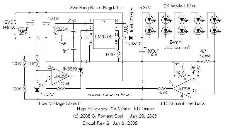
The heart of the circuit is a string of 10 white LEDs. These are wired in series and connected to a current-regulated step-up switching power supply circuit. DC powered LED lighting circuits can vary from the trivial, with a...
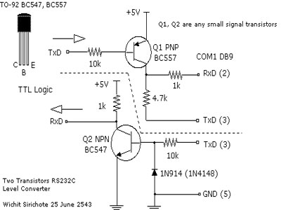
To connect a microcontroller project to the COM port of a PC, an RS-232 converter is required. Various chips are available to address this need, such as the MAX232 and DS275. The RS-232 standard is widely used for serial communication...
As the demand for VRM output current increases, the components and parts of the SR-Buck converter can no longer meet the requirements for the new generation microprocessors needing 100 A. Additionally, creating filtering inductance for high currents is quite...
The following circuit illustrates a Boost Converter Circuit Diagram. This circuit is based on the 555 IC. Features: it only requires off-the-shelf components. The Boost Converter is a type of DC-DC converter that steps up the input voltage to a...
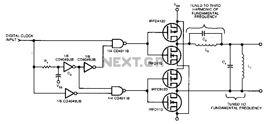
Two pairs of MOSFETs create a bridge that alternately switches current in opposite directions. Two parallel-resonant LC circuits complete the converter. The L1/C1 combination is resonant at the fundamental frequency, while the L2/C2 combination resonates at the third harmonic...
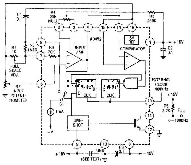
In this application, an AD652 integrated circuit (IC) is utilized in a synchronized voltage-to-frequency (V/F) converter that takes its input from the position of a potentiometer. This setup can represent the position of a mechanical component, weight, size, etc.,...
Warning: include(partials/cookie-banner.php): Failed to open stream: Permission denied in /var/www/html/nextgr/view-circuit.php on line 713
Warning: include(): Failed opening 'partials/cookie-banner.php' for inclusion (include_path='.:/usr/share/php') in /var/www/html/nextgr/view-circuit.php on line 713