
12V White LED Driver

The circuit design consists of a series connection of 10 white LEDs, which are typically rated for a forward voltage drop of approximately 3V each. This results in a total forward voltage requirement of around 30V when all LEDs are illuminated at their nominal current of 24mA. To achieve this voltage while maintaining efficiency, a step-up (boost) switching power supply is employed.
The power supply circuit utilizes a high-frequency switching regulator, which significantly minimizes power loss compared to traditional linear regulators or simple resistor-based current limiting methods. This is accomplished by rapidly switching the input voltage on and off, allowing the circuit to store energy in an inductor and release it at a higher voltage level.
In addition to providing the necessary voltage, the circuit includes current regulation features to ensure that the LEDs operate within their safe current limits. This is crucial for preventing thermal runaway and prolonging the lifespan of the LEDs. The current regulation is typically achieved through feedback mechanisms that monitor the output current and adjust the duty cycle of the switching regulator accordingly.
Moreover, an automatic shutoff feature is integrated into the circuit to protect the LEDs from excessive current in scenarios where the input voltage exceeds 12V. This is important for maintaining the integrity of the LED array and preventing potential damage from overcurrent conditions.
Overall, this circuit design exemplifies a balance between complexity and performance, offering enhanced control over light output and reliability while efficiently powering a string of LEDs.The heart of the circuit is a string of 10 white LEDs. These are wired in series and connected to a current-regulated step-up switching power supply circuit. DC powered LED lighting circuits can vary from the trivial, with a single LED and a series resistor, to more complicated switching power supply circuits such as this project.
There is a tradeoff between simplicity and circuit capabilities. This more complex circuit adds features such as a regulated light level and automatic circuit shutoff on low input voltage. The circuit also protects the LEDs from too much current when the supply rises above 12V. By using a high frequency switching regulator, the power loss associated with the current dropping resistors found in simpler circuits is eliminated. This offsets the power consumed by the extra active parts. This circuit can power 10 white LEDs at 24mA o 🔗 External reference
Related Circuits
An LED, or Light Emitting Diode, is a semiconductor device that allows current to flow in one direction while blocking it in the opposite direction. This characteristic makes LEDs polarized components, having a positive side known as the anode...
This circuit was designed as a warning flasher to alert road users to dangerous situations in the dark. Alternatively, it can act as a bicycle light. The circuit operates by utilizing a light-emitting diode (LED) as the primary visual alerting...
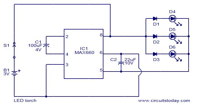
This circuit is a simple LED torch utilizing the MAX660 integrated circuit from MAXIM semiconductors. The MAX660 is a CMOS monolithic voltage converter IC capable of driving three bright white LEDs connected in parallel to output pin 8 of...
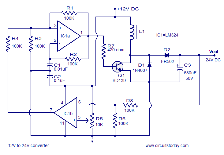
A simple 12V to 24V DC-DC converter circuit diagram built around the LM324. This boost converter schematic can provide up to 800mA output current and a steady 24V DC. The described circuit utilizes the LM324 operational amplifier as the core...
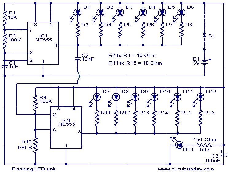
The circuit presented is designed as an LED flasher that creates a rotating effect when the LEDs are arranged appropriately. It operates with very low current consumption and can function using 3V button cells. The first integrated circuit (IC1),...
This analog switch utilizes the 2N4860 JFET, which features a low on-resistance (rON) of 25 ohms and minimal leakage current. The LM102 acts as a voltage buffer in the circuit. It is designed to be adaptable for use in...