
Multiple channel SR-Buck converter of the trimmer module VRM of voltage
The circuit diagram of a three-pathway SR-Buck converter is illustrated, featuring three SR-Buck converter modules. Each module consists of a main gas switching tube, a synchronous rectifier tube, a corresponding control driving circuit, and filtering inductance components L1, L2, and L3. The outputs of the three modules are interconnected, with interlocking control managing the voltage and current output, which is then directed to the output filtering capacitance. The drive pulses for the modules are interlocked and phase-shifted, with a phase difference of T/3, where T is the switching cycle of the module. This phase shift of 120 degrees among the three drive pulses helps to minimize current ripple among the inductive currents (iL1, iL2, and iL3). If the switching frequency of the module is set at 500 kHz, the ripple frequency of the output current would be 1.5 MHz.
The multi-channel SR-Buck converter serves as the primary circuit for the VRM. Compared to a single-channel configuration, this approach allows multiple Buck modules to be connected in parallel, enhancing output power, improving reliability, and maintaining low ripple frequency ranges for both output voltage and current. By reducing the filtering inductance, the transient response speed of the VRM is enhanced. The design of the multi-channel SR-Buck converter promotes uniform current distribution across modules, ensuring that thermal stress is evenly managed and minimizing the risk of damage due to excessive current in any single module. If each module operates in discontinuous mode, specialized current control is unnecessary; uniform duty ratios across modules suffice to achieve optimal current flow.As demand for VRM output current being bigger and bigger, the components and parts of SR-Buck converter can not already meet the demand for the microprocessor 100 A of new generation; In addition, the filtering inductance of making the heavy current is very difficult. Some literature is introduced: Make as output current for and 15 A filtering ind uctance want, it adopts external diameters to be 12. 7 mm 0. 5 in respectively at the 60 A Or 22. 86 mm 0. 9 in Toroidal core, wire respectively adopt 1. 291 mm 16 AWL Or 3. 264 mm 8AWG. Output current big and wire thick making toroidal core difficult inductance have. In order to solve this problem, it is heterogeneous Multi phase to research and develop one kind SR-Buck converter scheme, are called the multiple channel MulTI-channel SR-Buck converter, several pieces of SR-Buck converter module are connected in parallel, its output is adopted and interlockedinterleaving Control, phase shift control, unite, receive output at the Filtering capacitance. This kind of method can guarantee the output ripple of VRM is little, and tough because the filtering inductance of the output of every SR-Buck converter module is reduced, also improved the output transient response of VRM greatly.
Fig. 1 a It is the circuit diagram of 3 passway SR-Buck converters, there are 3 pieces of SR Buck converter module in the picture, each module is by main gas switching tube V, synchronous rectifier tube V, and corresponding control driving circuit And filtering inductance L1, L2 and L3 make up. 3 module fail the intersection of people and end meet, fail the intersection of people and the intersection of voltage and Ui export, adopt, interlock, control respectively, after 3 pieces of module are connected in parallel, receive on the Filtering capacitance of the output.
3 drive pulse of module interlock Phase shift Synchronous, 3 pieces of drive pulse phase difference T/ 3 T is the switch cycle of the module on time, Only 3 pieces of drive pulse phase shift are controlled, the phase place is mutually lack of 120 degrees so this kind of scheme is called the heterogeneous structure, make undulate iLl of 3 pieces of inductive current, iL2, iL3 lack of 120 degrees on the phase place each other too. The output current of VRM is Fig. 1 b Provide every module in 3 passway SR-Buck converters and interlock and control the inductive current undulate iL1, iL2, iL3 and output current io after connecting in parallel.
Suppose the switching frequency of the module is 500 kHz, then the ripple frequency of the output current is 1. 5 MHz. The multiple channel SR-Buck converter, as the main circuit of VRM, compared with single channel, its advantage is that a plurality of Buck module is connected in parallel, the output power is apt to expand, improve reliability, the high, ranges of ripple frequency of the output voltage and electric current are small.
When giving and exporting the voltage ripple, its filtering inductance can be reduced, thus has improved the transient speed of response of VRM. The measure of adopting connecting of the multiple channel SR-Buck converter in parallel to flow, in order to the uniform distribution of the electric current while guaranteeing the module, thermal stress is more even too, run and damage on the limiting current by preventing one or more of module.
If design every module work in the multiple channel SR Buck converter in the discontinuous mode, do not need specialized flow control, so long as control their duty ratio to be unanimous, can be in order to realize well that flows. 🔗 External reference
Related Circuits
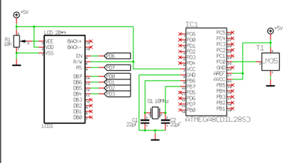
An Analog-to-Digital Converter (ADC) is a circuit integrated into a single chip designed to convert analog signals into digital signals. Typically, an 8-bit ADC chip converts an analog signal ranging from 0 to 5 volts into a digital level...
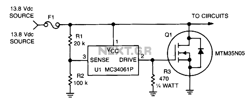
This circuit protects expensive portable equipment against all types of improper hookups and environmental hazards that could cause an overvoltage condition. It operates very quickly and does not latch up; rather, it recovers when the overvoltage condition is removed....
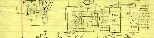
This example demonstrates the use of a pair of CD4051 multiplexers in parallel. The design incorporates elements from historical circuitry, particularly from Dave Jones' designs. This sequencer was constructed for a public access facility that primarily utilized a black...
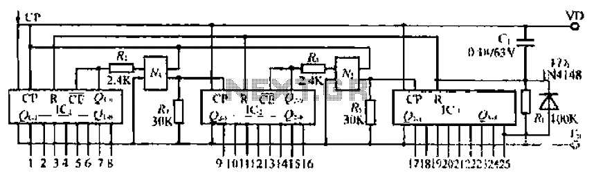
The CD4017B input signal is applied to the CP triggering pin. A pulse signal is sent through the IC, resulting in a straight-through output signal. The coupling device is used to control the input signal. When the power is...
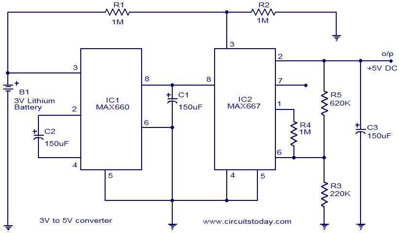
Voltage converter circuit diagram for converting 3 volts to 5 volts using CMOS monolithic ICs MAX660 and MAX667, which functions as a positive voltage regulator. The voltage converter circuit utilizes the MAX660 and MAX667 integrated circuits to step up a...
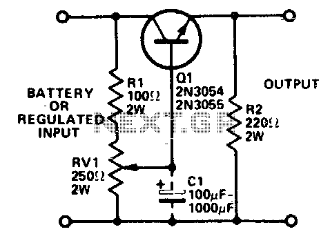
Integrated circuits (ICs) that require 3 or 6 volts can be powered from a battery or a fixed regulated supply with a higher voltage using the circuit illustrated. It is essential to mount the transistor on a heatsink, as...
Warning: include(partials/cookie-banner.php): Failed to open stream: Permission denied in /var/www/html/nextgr/view-circuit.php on line 713
Warning: include(): Failed opening 'partials/cookie-banner.php' for inclusion (include_path='.:/usr/share/php') in /var/www/html/nextgr/view-circuit.php on line 713