
6V Ultra-Bright LED Chasers

This project showcases an innovative use of LED technology to create a visually stimulating display while maintaining efficient power consumption. The circular arrangement of LEDs not only enhances the aesthetic appeal but also allows for dynamic light patterns that can be synchronized across multiple units. The CD74HC4017N IC serves as a key component, enabling the sequential activation of the LEDs with its 10 output channels. Its ability to handle brief output currents effectively prevents overheating, ensuring reliable operation.
The MC14584BCP IC contributes to the overall efficiency of the circuit, acting as a low-power oscillator that drives the LED sequences. Its high input resistance allows for the use of larger resistors, which is crucial in minimizing the total current draw from the power source. The design cleverly incorporates a Schmitt trigger oscillator configuration, which is essential for generating clean, stable clock pulses that control the timing of the LED flashes.
The brightness control mechanism, implemented through a PWM oscillator, allows users to adjust the intensity of the LEDs. This feature is particularly advantageous in extending battery life, as lower brightness settings result in reduced power consumption. The sample-and-hold stage, which captures the pulse driving LED #9, further enhances the control over the timing and duration of the LED flashes, allowing for a customizable user experience.
The physical assembly of the project is also noteworthy. The use of a compact disc as a mounting platform for the LEDs not only provides a stable base but also enhances the visual effect as the LEDs illuminate in a circular motion. The integration of a plastic box to house the circuit and battery holders ensures that the components are well-protected and organized. The multiconductor ribbon cable facilitates easy connections between the LEDs and the circuit, simplifying the assembly process.
Overall, this project exemplifies creativity in electronic design, merging functionality with visual appeal while prioritizing energy efficiency. The thoughtful selection of components and configuration strategies results in a unique and engaging LED display that can be enjoyed in various settings.This is a spectacular but completely useless project. It lights Ultra-Bright LEDs in a sequence and each LED flashes brightly very briefly. The LEDs light-up going around and around since they are mounted in a circle (on a CD), then they pause before chasing again. The very brief flash of each LED (15ms) and the pauses (1 second) reduce the averag e current so the battery should last a long time. For user convenience, this project has a stepper speed control and a brightness control. At slower speeds and/or reduced brightness, the battery ’s life is extended considerably. At full brightness, the LEDs flash extremely brightly. More than one of this project grouped together occasionally synchronize, lighting the whole room for a moment. At maximum speed, the LEDs don ’t appear to flash, instead they appear to move from one lighted one to the next, around and around.
They rotate completely for 4 rotations in two seconds, and then turn off for a one second pause then repeat the sequence. At a lower speed, the number of rotations before the pause is less. It will do three rotations, two or even only one rotation at its slowest speed. A sequence of rotations starts with LED #2 and end with LED #9. The CD74HC4017N high-speed Cmos IC is rated for a maximum supply voltage of 7V. It is rated for a maximum continuous output current of 25mA. In this project, the maximum supply voltage is 6. 4V with brand new battery cells and the 24mA output current is so brief that the IC runs cool. The MC14584BCP* IC (Motorola) is an ordinary 4XXX series ” 3V to 18V Cmos IC, with a very low operating current and low output current.
Its extremely high input resistance allows this project to use high value resistors for its timers and oscillators, for low supply current. Its 6 inverters are Schmitt triggers for simple oscillators and very quick switching. IC2 is a 10 stage Johnson counter/decoder. On the rising edge of each clock pulse its outputs step one-at-a-time in sequence. It drives the anode of each conducting LED toward the positive supply. IC1 pins 1 and 2 is a Schmitt trigger oscillator with C3 and C4 paralleled for a very low frequency. R1 and R2 control its frequency and the diodes with R3 combine with the capacitors to produce the 15mS on time for the LEDs.
IC1 pins 5 and 6 is the brightness Pulse Width Modulation oscillator. The pot R7 with the associated diodes and resistors allow it to change the duty-cycle of its output for PWM brightness control. It drives the transistor. IC1 pins 3 and 4 is an inverter. It takes the low time (LEDs off) from the clock oscillator, inverts it to a high and shuts-off the brightness oscillator through diode D6.
IC1 pins 11 and 10 is a sample-and-hold stage. It takes a sample of the pulse driving LED #9 though D3 and R4 and charges C5 in steps. At maximum speed it takes 4 steps for C5 to charge to the Schmitt switching threshold voltage. R5 and D5 slowly discharge C5 for the pause time. The 10 LEDs mount on a Compact-Disc which is glued to a plastic box with contact cement. The box houses the Veroboard circuit in its lower main part with the battery holders on its lid. Multiconductor ribbon cable joins the LEDs to the circuit. The pots mount on the sides of the box. In addition to these changes, R8 = 680 ohms and R9 = 22 ohms. I built one using low-voltage (1. 8V at 20mA) orange Ultra-Bright LEDs. The orange one looks good beside the green one. I wish I knew how to take a slow picture with my son ’s digital camera, so all the LEDs would be lighted, and if I moved it would make nice lighted smears in the picture. 🔗 External reference
Related Circuits

This chip from Texas Instruments is easy to integrate into designs and is suitable for the assembly of lighting devices. A consistent quality and expected performance can be easily achieved. The complete circuit consists of a control integrated circuit...
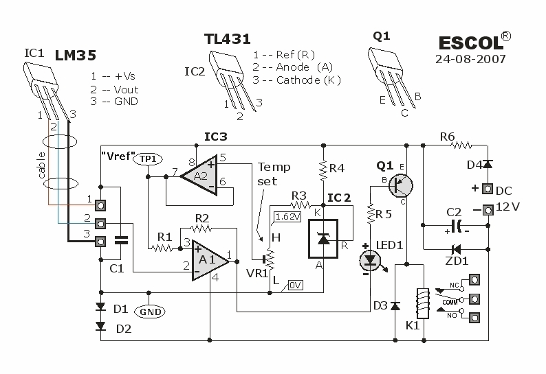
This temperature-controlled relay circuit is a simple yet highly accurate thermal control circuit that can be used in applications where automatic temperature regulation is required. The temperature-controlled relay circuit operates by monitoring the ambient temperature using a temperature sensor, such...

The voltage to be measured is digitized in an analog-to-digital (A/D) converter and then displayed in three decimal digits. The display consists of three groups of 10 LEDs. The meter can only be used for measuring direct voltages. The...

The CSL310L is a dual-color LED that incorporates a red LED and a green LED arranged back to back within a single housing. This LED can emit either red or green light depending on the polarity of the applied...

The primary function of the frequency counter is to measure the frequency and cycle of a signal. Its applications span a wide range, extending beyond simple instrument measurements to areas such as education, scientific research, high-precision instrument measurement, and...

This circuit is designed as a warning flasher to alert road users to dangerous situations in low-light conditions. It can also function as a bicycle light, adhering to traffic regulations. White LEDs are recommended for use as a front...