
Digital Led Voltmeter
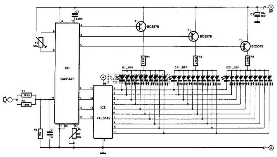
The described circuit employs an analog-to-digital converter (A/D) based on the CA3162T, which is designed for precise measurement of direct voltage levels. The converter's full-scale deflection (FSD) is originally set to 999 mV, which is suitable for low-voltage applications. To accommodate higher voltage measurements, a potential divider is implemented using resistors R1, R2, and R3. This configuration allows the circuit to extend its measurement capability to a maximum of 10 V by scaling down the input voltage appropriately.
The output of the A/D converter is represented on a display comprised of three groups of 10 light-emitting diodes (LEDs). Each group corresponds to a specific digit in the measured voltage value. The first group (D1 through D10) displays the unit's place, the second group (D11 through D20) represents the tens place, and the third group (D21 through D30) indicates the hundreds place. This arrangement provides a clear and straightforward visual representation of the measured voltage.
To ensure accurate readings, the circuit includes a nulling feature facilitated by potentiometer P1. When the input is disconnected, the circuit is adjusted to display zero volts, indicated by the illumination of the first LEDs in each group (D1, D11, and D21). The design also incorporates a calibration mechanism; after applying a known reference voltage, potentiometer P2 is adjusted to align the LED display with the expected voltage level.
The circuit is designed to handle specific operational conditions. If the measured voltage exceeds the maximum input range, the display will deactivate to prevent damage or erroneous readings. Additionally, the circuit is not capable of measuring negative voltages, as indicated by the non-illumination of the unit LEDs under such conditions. It is important to note that fluctuations in the supply voltage can adversely impact the accuracy of the measurements, necessitating stable and regulated power supply conditions for optimal performance. The voltage to be measured is digitized in an analog-to-digital (A/D) converter and then displayed in three decimal d igits. The display consists of three groups of 10 LEDs. The meter can only be used for measuring direct voltages. The A/D converter is based on CA3162T which can process direct voltage up to 999 mV (1-V full-scale deflection—FSD). The FSD is extended to 10 V with the aid of potential divider R1/R2/R3. Other ranges are possible by altering the values of the resistors. The measured value is read from three bars of LEDs: the first one of these, Dl through D10, shows units; the second, Dll through D20 tens; and the third, D21 through D30, hundreds.
The circuit is nulled with PI when the input is open. Zero here means that diodes Dl, Dll, and D21, light. Diodes D10, D20, and D30, represent the figure 9. Next, a known voltage is applied to the input and P2 is adjusted until the LEDs read the correct value. When the input voltage is too high, the display goes out. When the input is negative, the unit LEDs do not light. Notice that variations in the supply voltage affect the measurement adversely. 🔗 External reference
Related Circuits
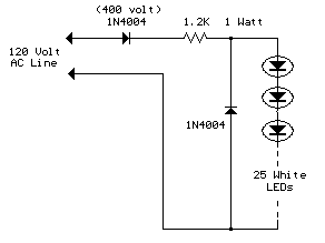
The LED circuit illustrated below features 25 white LEDs connected in series to a 120VAC power supply. This configuration can be adjusted to accommodate a different number of LEDs by modifying the resistor value. The specific resistance required will...

Although analog and digital controllers may seem vastly different, their principles of operation are often quite similar. Therefore, popular analog tools like Spice can still be utilized to enhance common digital proportional-integral controllers through analysis, without the need for...

A simple LED voltmeter is designed to monitor the charge level in a lead-acid battery or tubular battery. The terminal voltage of the battery is displayed using four LED indicators. The nominal terminal voltage for a lead-acid battery is...
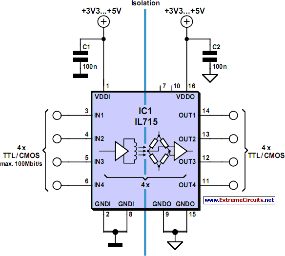
When it is necessary to transmit a digital signal between two electrically isolated circuits, an optoisolator or transformer coupling is typically employed. However, both solutions have limitations; optocouplers are effective only up to approximately 10 MHz, while transformers exhibit...

A bridge circuit is utilized to generate a signal from the output of vacuum sensor IC1. IC2b introduces an approximate 0.2 V offset for IC4, the A/D converter. IC2b and IC2d function as voltage followers that drive the differential...
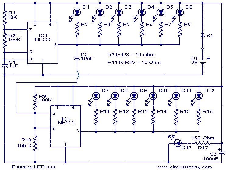
The circuit presented is designed as an LED flasher that creates a rotating effect when the LEDs are arranged appropriately. It operates with very low current consumption and can function using 3V button cells. The first integrated circuit (IC1),...