
Temperature Controlled Relay Circuit
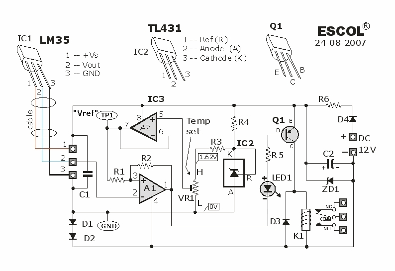
The temperature-controlled relay circuit operates by monitoring the ambient temperature using a temperature sensor, such as an NTC thermistor or a thermocouple. The sensor provides an analog voltage or resistance change that correlates to the temperature. This signal is fed into a comparator or microcontroller that compares the sensed temperature against a predefined setpoint.
When the sensed temperature exceeds the setpoint, the comparator output changes state, activating a relay. This relay can control larger loads, such as heaters or cooling systems, by switching them on or off based on the temperature readings. The relay's contacts can handle the necessary current and voltage for the application, ensuring safe operation.
The circuit may include additional features such as hysteresis to prevent rapid on-off cycling of the relay, which can prolong the lifespan of the relay and improve system stability. A potentiometer can be used to adjust the setpoint, allowing for flexibility in temperature control.
Furthermore, a LED indicator could be incorporated to visually indicate the status of the relay, providing an intuitive understanding of the circuit's operation. Power supply considerations must also be taken into account, ensuring that the circuit operates within the specified voltage range for all components involved.
In summary, this temperature-controlled relay circuit is a versatile solution for applications requiring precise thermal management, offering reliable performance and ease of integration into various systems.This temperature controlled relay circuit is a simple yet highly accurate thermal control circuit which can be used in applications where automatic tempera.. 🔗 External reference
Related Circuits
Figure 2-33 (a) illustrates the schematic diagram of a robot approaching an object. When no objects are detected in front of the robot, it moves forward in a straight line. If an object is detected on the left or...
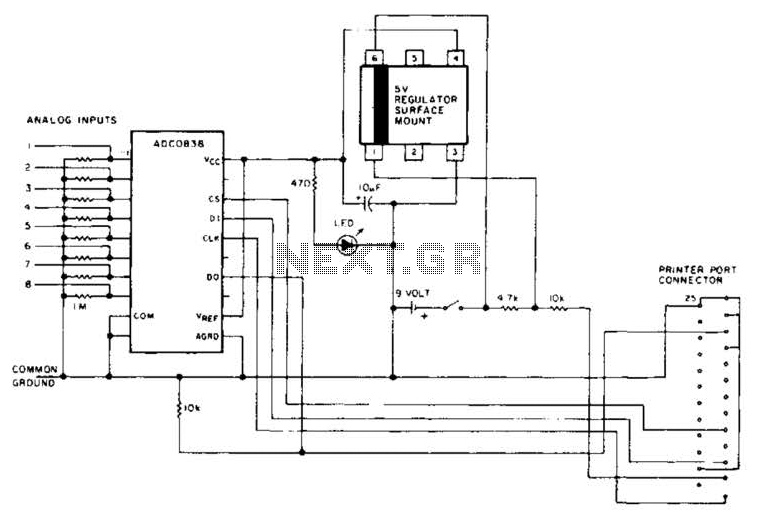
An A/D converter by National Semiconductor (ADC0838) converts 0 to 5 V analog inputs into a digital data format. A 9 V battery is utilized. The converter connects to the pointer port connector through a 25-pin connector. The ADC0838 is...
Automatic door control systems typically have a high market price for finished products. The proposed method is suitable for home use, utilizing easily accessible components. This design is ideal for those interested in creating their own automatic door system....
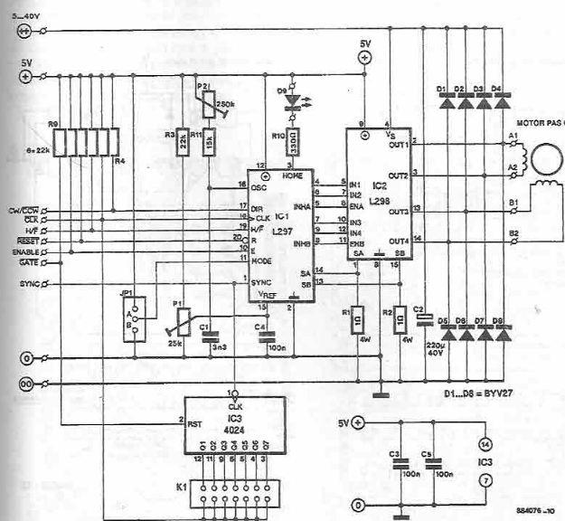
The L297 and L298 integrated circuits manufactured by SGS Thomson (ST) can be utilized to create a control circuit for a stepper motor, accommodating both two-phase bipolar and unipolar four-phase configurations, with a maximum current rating of 2 A...
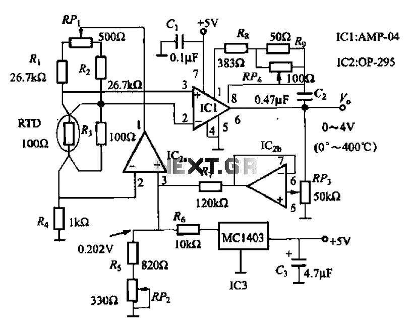
AMP-04 is a single-supply, single resistor gain adjustment circuit with an input voltage drift of less than 150 pV, a current drift of 5 nA, and a temperature drift of 8 pA/°C. The gain nonlinearity is 0.005% of the...
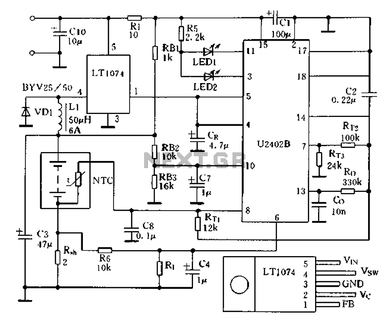
Charging circuit from the DC power supply switching power supply control The charging circuit described is designed to operate with a DC power supply, utilizing a switching power supply control mechanism. This type of circuit is commonly employed in applications...