
6W Warble-Tone Siren

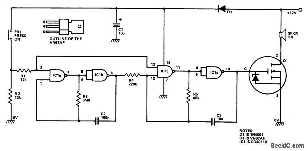
The circuit is designed to deliver audio amplification with a specific focus on efficiency and power output. The CMOS chip serves as the core component for generating the necessary oscillator signals, which are critical for the operation of the audio amplifier. The 1-Hz oscillator formed by IC1A and IC1B provides a low-frequency signal that is essential for timing applications within the circuit, ensuring that the system operates in a synchronized manner.
The 1-kHz multivibrator, constructed using IC1C and IC1D, receives its gating signal from the 1-Hz oscillator. This multivibrator is responsible for generating a higher frequency output that can be used to modulate the audio signal. The gating mechanism allows for precise control over the timing and characteristics of the output waveform, which is crucial for audio fidelity and performance.
The VMOS FET amplifier is utilized for its high efficiency and ability to handle significant power levels. With a power supply of +24 Vdc, the amplifier can produce up to 18 W of audio output, making it suitable for various audio applications. The design ensures that the amplifier operates within its optimal range, minimizing distortion and maximizing sound quality.
In summary, this circuit integrates a CMOS chip and a VMOS FET amplifier to create an efficient audio output system capable of delivering substantial power while maintaining audio quality. The use of oscillators and multivibrators provides essential timing and modulation capabilities, enhancing the overall performance of the audio amplification circuit. This circuit uses a CMOS chip and a VMOS FET amplifier for 6 W of audio output. 18 W of audio can be generated using a + 24-Vdc supply. IC1A and IC1B are used as a 1-Hz oscillator. IC1C and IC1D form a 1-kHz multivibrator that is gated by the 1-Hz signal from IC1A and IC1B.
Related Circuits
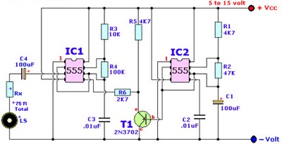
Browse home alarm circuit explanation latest schematic siren wailing with latest Wailing Alarm Siren circuit schematic with explanation. The loudspeaker LS and the resistor marked Rx should be together 75 ohms. If a standard 8-ohm speaker is used, then...
IC1a and IC1b are configured as a slow astable multivibrator, while IC1c and IC1d are set up as a fast astable multivibrator. Both configurations are of the "gated" type, allowing them to be activated or deactivated through push button...

This is a siren sound generator circuit that is cost-effective and capable of producing simple sound patterns. The circuit utilizes IC1, which is a CD4011 (Digital NAND Gate), and IC2 is... The siren sound generator circuit is designed to produce...
The circuit utilizes IC1 to create an astable multivibrator configuration. It is designed to generate a low-frequency output of approximately 1 Hz at pin 3, which is determined by the resistor values R1, R2 and capacitor C1. The output...
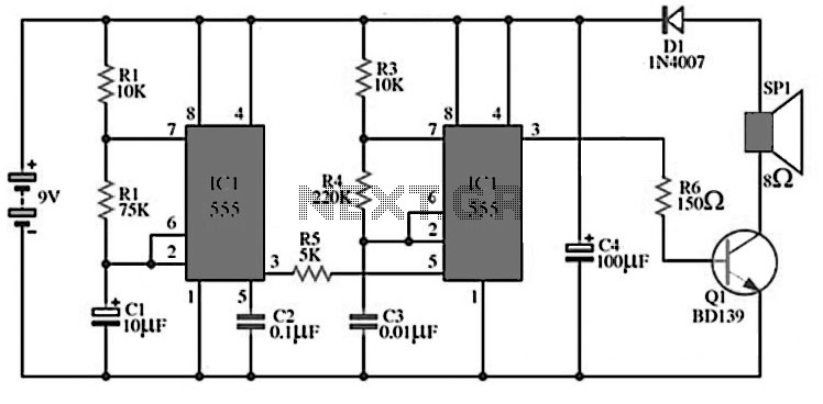
Assortment of siren circuits. This month, three different types of siren circuits are being created based on the 555 timer. The first circuit simulates the siren of a British police car. It utilizes two 555 timers. The design of the...
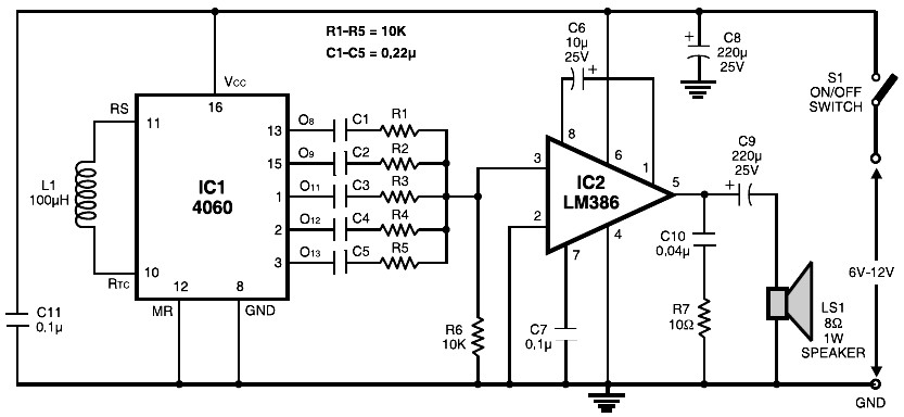
The circuit is built around the popular CMOS oscillator-divider IC 4060 and a small audio amplifier LM386. The IC 4060 functions as a multitone generator. A 100 H inductor is used at the input of the IC 4060, allowing...