
latest Wailing Alarm Siren circuit Schematic with explanation

The Wailing Alarm Siren circuit is designed to produce a loud, attention-grabbing sound, typically used in security systems or alert mechanisms. At the heart of this circuit is a loudspeaker (LS) which requires an appropriate resistor (Rx) to ensure optimal performance and sound quality. The combination of the loudspeaker and the resistor should total 75 ohms to achieve the desired output.
For an 8-ohm loudspeaker, the calculated resistor value is 67 ohms. However, in practice, the nearest standard resistor value of 68 ohms is recommended. This small adjustment helps to maintain the integrity of the sound produced while ensuring the circuit operates safely without overloading the components. Similarly, for a 4-ohm loudspeaker, a resistor value of 71 ohms is suggested, while for a 25-ohm loudspeaker, a resistor value of 50 ohms is appropriate.
The circuit may include additional components such as transistors, diodes, or capacitors to enhance functionality, control the sound output, or manage power distribution. Each component plays a critical role in the overall performance of the siren, ensuring that it can produce a loud, wailing sound that effectively alerts individuals in the vicinity. Proper selection of these components is essential for achieving the desired performance characteristics of the alarm system.Browse » home » alarm » circuit » explanation » latest » schematic » siren » wailing » with » latest Wailing Alarm Siren circuit Schematic with explanation *The Loudspeaker LS and the resistor marked Rx should be together 75 ohms. If you have a standard 8-ohm speaker then Rx is 67 ohms. The nearest value is 68 ohms. So for a 8 ohm lou dspeaker Rx is 68 ohms. For a 4 ohm loudspeaker Rx is 71 ohms, for a 25 ohm loudspeaker Rx is 50 ohms, etc, etc. 🔗 External reference
Related Circuits
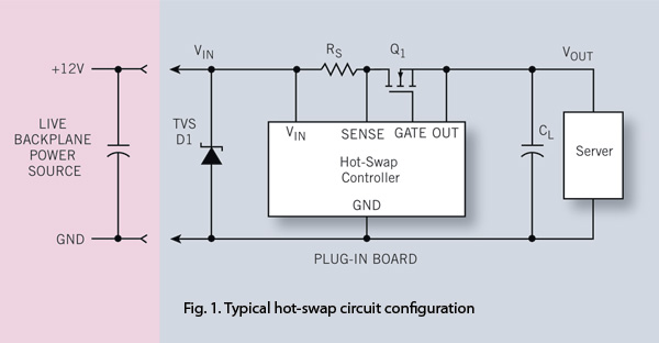
To ensure reliability, the server system designer must take into account the parasitics of hot-swap circuits and their associated transient behavior. It is recommended that a transient voltage suppressor (TVS) diode clamp be utilized at the line card input....
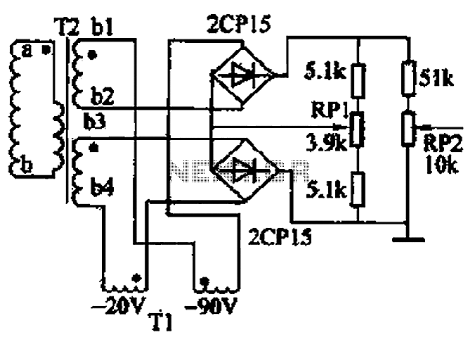
The closed-loop system consists of longitudinal and transverse components. The circuit operates as follows: a control circuit from the stepping motor CNC system issues a command, which the receiver detects. This signal is processed through a phase-sensitive rectifier to...
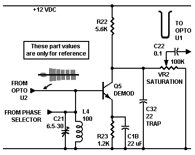
The circuit is an amplifier with bias at cutoff. Transistor Q5 functions similarly to a grid-leak detector. In the absence of a subcarrier input, the demodulator is disabled, preventing any signals from passing through. It is essential for the...
A video switcher circuit is required to display multiple sources on a single monitor. The circuit schematic below features the MAX454, which serves as the core component of this video switcher. The MAX454 is a video multiplexer-amplifier manufactured by...
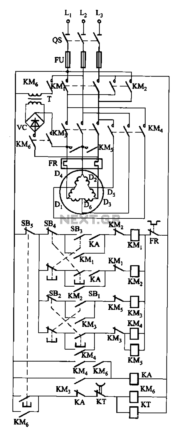
The circuit depicted in Figure 3-108 includes various control buttons: SB3 for the forward button, SI for the reverse button, SBi as the low start button, SB2 for the speed start button, and SBs for the stop button. KMs...
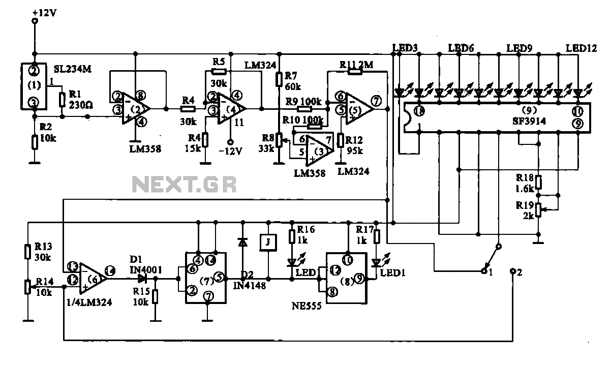
Vegetable greenhouse temperature detection control circuit. The greenhouse temperature detection control circuit is primarily composed of a temperature sensor SL234M, operational amplifiers LM324 and LM358, a dual time base circuit NE555, a relay, and a display driver circuit. The...