
7 Segment Digital Clock Circuit Using IC 5314 PCB

The digital clock circuit primarily features the MM5314 integrated circuit, which is specifically designed for timekeeping applications. This IC is capable of generating accurate time signals and driving the common anode seven-segment displays directly. The circuit is configured to operate at standard power line frequencies of either 50 Hz or 60 Hz, ensuring compatibility with various electrical systems worldwide.
The common anode seven-segment displays used in this circuit consist of seven individual segments for each digit, allowing for the representation of numerals from 0 to 9. Each display is connected to the MM5314, which controls the illumination of the segments based on the current time values. The configuration allows for a clear and easy-to-read time display, suitable for various environments.
The clock can be set to display time in either a 12-hour or 24-hour format, which can be selected based on user preference. This feature adds flexibility and convenience for users accustomed to different timekeeping styles. The MM5314 IC manages the timekeeping logic, including the counting of seconds, minutes, and hours, while also providing reset functionality for setting the time.
This digital clock circuit is an excellent choice for educational purposes, particularly for college students engaging in electronics projects. Its simplicity, combined with the absence of complex components such as microcontrollers, makes it an ideal project for learning about digital electronics and timekeeping mechanisms. The design emphasizes fundamental concepts such as frequency division, binary counting, and display driving techniques, all of which are crucial in the field of electronics.This circuit diagram of digital clock uses six common anode seven segment displays to show the time. It needs neither micro controllers or PIC for it`s operation. It`s a MM5314 IC driven digital clock operating at 50 Hz or 60 Hz, and 12 or 24 hour display format. It`s very suitable for college mini projects. 🔗 External reference
Related Circuits
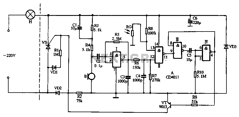
The circuit utilizes CD4011 digital circuits to create a sound-activated light lamp with a dual-control delay section. The left portion of the circuit represents the lighting lines, while the right part consists of the sound and light control delay...
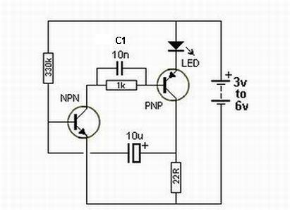
Oscillation is expected at the resonant frequency where the positive feedback is in phase with the input, specifically at 0 degrees. For oscillation to take place, the gain must be equal to or greater than 1 at that frequency....
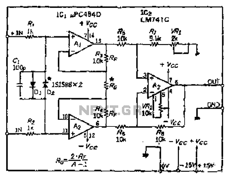
All resistance values are equal, resulting in the Cantonese operational amplifier's gain (A) being equal to 1. However, by selecting smaller resistances, the gain can be adjusted. The circuit can achieve the desired gain through six configurations. Two heavy...
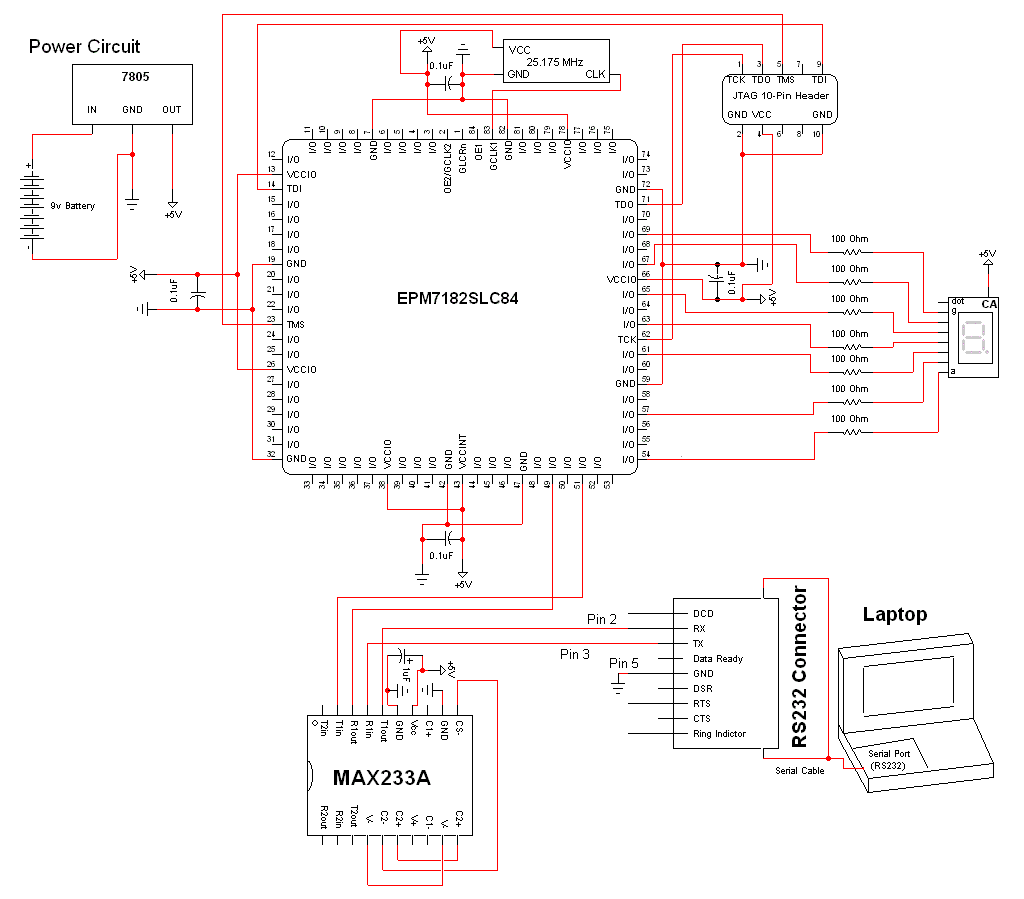
The schematic for this project is a modified version of the CPLD development board schematic. Several new components have been added for this project, and the completed schematic can be viewed below. The main components in the schematic are...
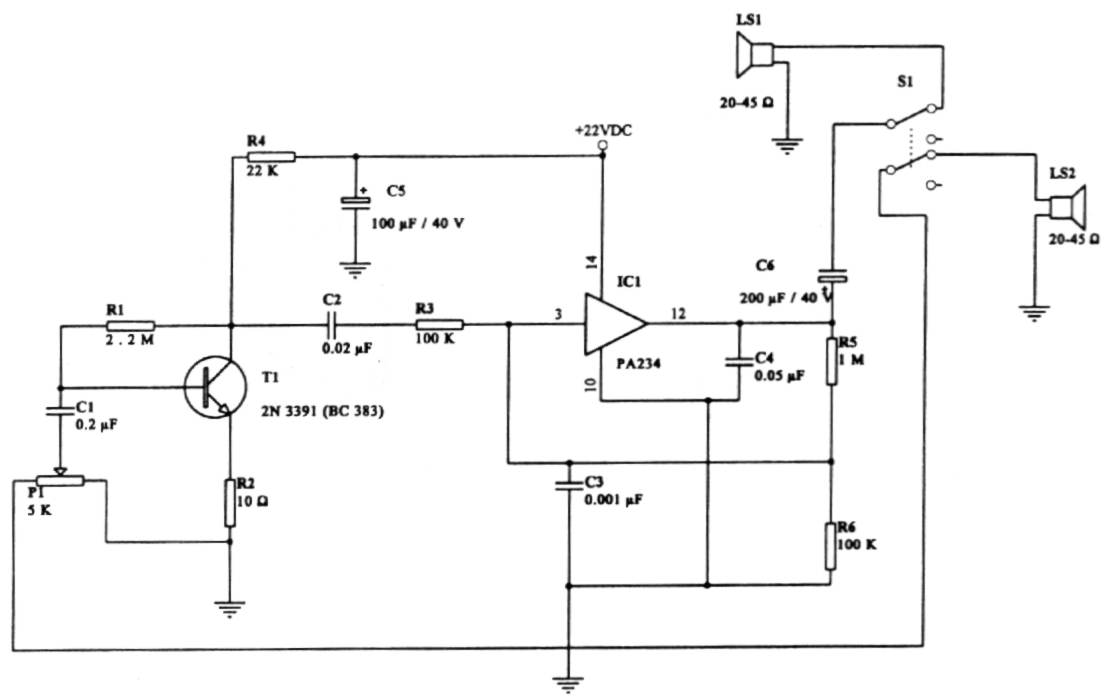
This intercom circuit is versatile and can be utilized in various applications. It operates at 22V, although it may function at a lower voltage (experimental testing is suggested). The circuit utilizes a loudspeaker with an impedance of 20-45 Ohms...
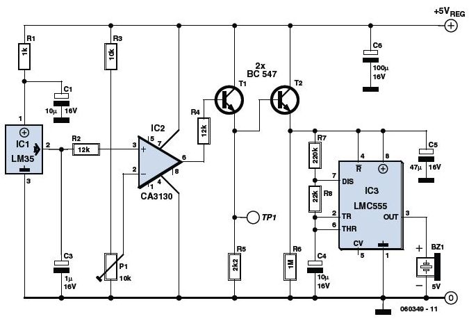
This is an Overheat Detector Alarm Switch using the Temperature Sensor IC LM35. The core of this overheat detector (fire alarm) circuit is a precision integrated temperature sensor, the LM35 (IC1), which provides an accurately linear and directly proportional...