
741 Stereo PreAmplifier

The 741 stereo preamplifier circuit is designed to amplify audio signals with a gain of over 20 dB in each channel, making it suitable for various audio applications. The circuit utilizes the popular 741 operational amplifier, which is known for its versatility and reliability in audio processing.
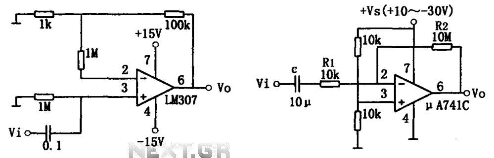
The basic configuration includes two channels, each consisting of an input resistor (R1), feedback resistor (R2), and coupling capacitors to block DC offsets. The gain of each channel can be adjusted by varying the values of R1 and R2, allowing for customization based on the specific requirements of the audio source and desired output level.
In addition to the resistors, the circuit may include bypass capacitors to enhance frequency response and stability. Proper power supply decoupling is also essential to minimize noise and ensure consistent performance. The circuit can be powered by a dual power supply, typically ±15V, to accommodate the operational amplifier's requirements.
The output of the preamplifier can be connected to a power amplifier or other audio processing equipment. It is important to ensure that the output impedance matches the input specifications of the subsequent devices to maintain signal integrity.
Overall, the 741 stereo preamplifier circuit is a robust solution for enhancing audio signals, providing significant gain while maintaining sound quality. Proper component selection and circuit layout are crucial for achieving optimal performance and minimizing interference.741 Stereo PreAmplifier Circuit Diagram This preamp circuit provides better than 20dB gain in each channel. PARTS LIST R1 -.. 🔗 External reference
Related Circuits
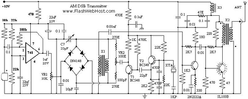
This circuit illustrates the LM741 Ham Radio Circuit Diagram. Features include AM, FM, 7 MHz SSB Transceiver, FSM, dummy load, and DSB transmitters. The LM741 operational amplifier is a versatile component widely used in various analog applications, including ham radio...
The simple audio amplifier circuit is illustrated in the figure. Utilizing an integrated op-amp configuration, this audio amplifier is stable and allows for easy negative feedback, facilitating the achievement of equalization characteristics. Additionally, the crosstalk between channels is minimal,...
This is a circuit diagram designed for high voltage DC impedance. It utilizes the uA741 integrated circuit (IC), which functions as a non-inverting DC amplifier. The circuit incorporates negative feedback through DC meters to achieve a full-scale deflection of...
The TDA2822 is a low-power stereo operational amplifier commonly utilized in Walkman devices and headphones. It is capable of delivering an output power of 250 milliwatts. This operational amplifier is particularly suitable for low-volume production applications and serves as...

This is a light sensor circuit designed to detect darkness, utilizing the op-amp 741 integrated circuit as the primary control element. The circuit is straightforward and specifically designed to sense light during nighttime. The light detection is accomplished using...
Design and dimensioning of active low-pass and high-pass filters using Sallen-Key and multiple feedback topologies. Spice netlist generator. Active low-pass and high-pass filters are essential components in signal processing, allowing specific frequency ranges to pass while attenuating others. The Sallen-Key...