
Simple audio amplifier LM307 A741
This audio amplifier circuit is designed for versatility and efficiency in audio signal processing. The dual power supply configuration in Figure (a) allows for a stable operation with the LM307N op-amp, which is well-suited for audio applications due to its low noise and high gain characteristics. The use of a coupling capacitor (0.1 µF) ensures that only the AC components of the audio signal are amplified, while blocking any DC offset that could affect performance.
In contrast, the single power supply configuration in Figure (b) simplifies the power requirements, making it suitable for battery-operated devices. The design effectively manages the DC offset through the implementation of negative feedback, ensuring that the amplifier maintains a linear response across the audio frequency range. The choice of feedback components (R1 and R2) is crucial, as they define the gain and frequency response of the amplifier. The gain equation highlights the inverse relationship between R1 and R2, allowing for precise control over amplification levels.
Moreover, the low-frequency characteristics of the circuit can be tailored by adjusting the values of R1, R2, and the coupling capacitor C, which can be particularly beneficial in applications requiring specific equalization or filtering of audio signals. The design also minimizes crosstalk, enhancing the quality of mixed audio inputs and ensuring a clearer output.
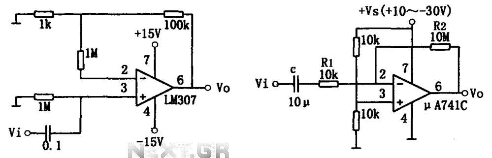
Overall, this simple audio amplifier circuit is a robust solution for various audio applications, providing stable amplification with minimal interference and the flexibility to accommodate different signal conditions. As shown in FIG simple audio amplifier circuit. Using the integrated op-amp configuration of audio amplifier is stable, easy to negative feedback, so it is easy to get equaliza tion characteristics. In addition, crosstalk between channels is small, it is also very easy to mix multiple input channels. Figure (a) shows a circuit using a dual power supply (Vs 15V), with the phase-inverting input terminal, respectively, to ground the static balance resistance, the input signal Vi by the 0.1 F coupling capacitor into LM307N-inverting input terminal (Cited 3 feet).
The signal source, the input resistance of about 1M, and therefore the equivalent load is light. The circuit voltage is about 101 times magnification, and has good dynamic characteristics. Figure (b) shows a circuit using a single power supply, because the DC level signal problem does not exist in the AC amplifier, so this power supply is desirable. In this circuit, the audio signal via a coupling capacitor C K and resistor R1 fed, A741C inverting input (pin 2).
The figure shows that the circuit for DC component is introduced 100% negative feedback (c DC component is quite open), so the offset voltage without amplification. The voltage of the circuit magnification: Av -R2/R1 -1000 (ie 60dB). It should be emphasized that: R1, R2 and capacitor C having low frequency attenuation and phase shift effect, when the signal frequency is low, may be appropriate to increase the capacitance C of capacity.
Related Circuits
One of the most notable RF amplifiers documented is Wes Hayward's post-mixer amplifier in the Progressive Communications Receiver. It is recognized as a highly effective high-level RF amplifier, operating with a standing current of 50 mA, which allows it...
Designing an audio amplifier from scratch using discrete components is an engaging task, as it enables users to create amplifiers that meet diverse requirements. Audio amplifiers can enhance low-level sounds from mobile devices, making them louder and more vibrant....
Adapting a failed Tesla coil into a crystal radio set for demonstration purposes has presented challenges, particularly with antenna size for optimal signal reception. It has been noted that an ideal AM antenna should range between 100 to 500...
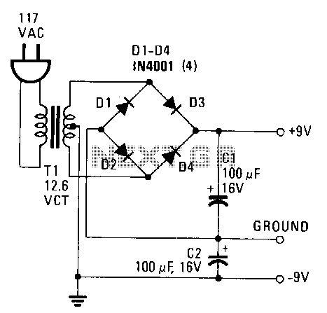
This power supply provides both +9 V and -9 V outputs to replace two 9-V batteries. The rectifier circuit consists of two separate full-wave rectifiers, each connected to the secondary winding of the transformer. The first full-wave rectifier, made...
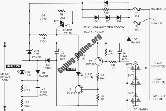
This circuit design features a modular arrangement that enables users to select only the modules best suited to their needs, allowing for the construction of a chain ranging from one to five modules in length. For those seeking a...
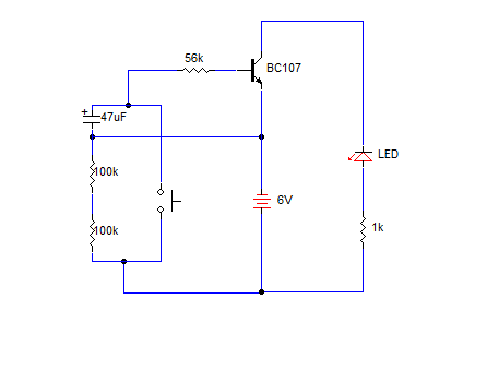
A simple transistorized one-minute delay timer circuit. It does not include any complex or critical components. This circuit can generate a time delay of approximately one minute. When the switch (preferably a push-button type) is pressed, the LED turns...