
Light Sensor Circuit Using Op Amp 741

The light sensor circuit operates effectively by leveraging the characteristics of the LDR and the op-amp. The LDR's resistance varies inversely with the intensity of light; as light levels drop, the resistance increases, which is critical for the functioning of this circuit. The op-amp 741 is configured in a comparator mode where it compares the voltage at pin 2 (connected to the LDR) with a reference voltage at pin 3. When the voltage at pin 2 exceeds the reference voltage, the output at pin 6 goes high, turning on the transistor Q1, which in turn activates the relay.
The inclusion of the trimmer potentiometer P1 allows for fine-tuning of the sensitivity, making it adaptable to different ambient light conditions. The use of resistors R2 and R3 in conjunction with P1 ensures that the voltage divider can be adjusted to set the threshold at which the sensor activates.
For applications requiring the reverse functionality—detecting darkness instead of light—the simple modification of swapping the LDR and resistor R1 allows for this. This flexibility makes the circuit versatile for various use cases, such as automatic streetlights or security lighting.
The addition of resistor R6 introduces hysteresis, which is essential in preventing the relay from rapidly switching on and off due to minor fluctuations in light levels. This is particularly useful in environments where light conditions may vary frequently, such as near streetlights or during twilight.
Diode D1 is crucial for protecting the circuit from voltage spikes generated when the relay contacts open, ensuring the longevity and reliability of the circuit components. The overall design operates on a 12 V DC power supply, making it suitable for integration into various electronic systems requiring low-voltage operation.This is a one of the light sensor. This circuit is a dark sensor that is based on op amp 741 IC as main control. This circuit is a simple design for sensor the light at the night. This is the figure of the circuit. For sensor the light is using LDR. Operation of the circuit is under normal conditions the resistance of the LDR is high, keeping pin 2 low. When light falls onto the LDR the resistance drops to a couple hundred ohms and triggers pin 2 high which biases the base of Q1 via pin 6 and R4 and in turn activates the relay. Trimmer pot P1 and the two 470 ohm resistors, R2 and R3, are a voltage divider to adjust for sensitivity.
If you want the action reversed (make it a dark sensor), change the positions of the LDR and R1. If the relay chatters, add a bit of hysteresis by adding a 100K to 1Meg-ohm resistor (R6) over pins 6 and 2 of the 741 op-amp, but in most cases 100K to 330K will do the job. The LDR is a regular, general purpose type. D1 serves as a spark-arrestor when the relay contacts open. This circuit power supply is using 12 V DC. 🔗 External reference
Related Circuits

This 6V battery-operated doorbell light circuit can be connected in parallel with any existing AC 230V doorbell. When the doorbell switch is pressed, the bell sounds as usual, and the AC mains supply available across the doorbell is routed...
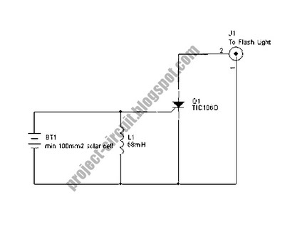
The following circuit illustrates a Slave Flash Light Control Circuit Diagram. Features include a 68 mH inductor, which provides an automatic trigger for the secondary flash light. The Slave Flash Light Control Circuit is designed to enhance the functionality of...
The described shunt-feedback configuration facilitates the straightforward incorporation of frequency-dependent networks, enabling a practical and unobtrusive switchable tilt control as an optional feature. When switch SW1 is in the first position, a gentle shelving bass boost and treble cut...
This is a circuit that ensures that you can connect two amplifiers together so you get more power. When called in bridge linking two amplifiers plus you can link the outputs of the amplifiers to the speaker. One of...
This circuit diagram represents an ECM Mic Preamplifier. It is a microphone amplifier compatible with Electret Condenser Microphones (ECM). The preamplifier exhibits an excellent dynamic range, capable of handling audio levels from a whisper to a scream; however, caution...
An inverting mode amplifier is required for precision accelerometers due to their typical charge output characteristics. This amplifier is utilized to convert charge into voltage. An inverting mode amplifier is a critical component in applications involving precision accelerometers, which often...