
75 meters Band SSB transceiver
The transceiver circuit described operates in both receive and transmit modes, utilizing a combination of band pass filters (BPF), amplifiers, and switches to facilitate signal processing. The core architecture includes two SA602 integrated circuits, which serve as the primary mixers for the transceiver. The design employs a 4-element 1500 ohm crystal BPF that is strategically switched between the input and output paths of these mixers to enable seamless switching between reception and transmission.
In the receive path, a 50 ohm antenna connects to the half-pi BPF with a quality factor (Q) of 5, which filters incoming signals before they reach the receive-transmit (R/T) switch. Following the switch, the signal is amplified by a 2N2222 RF amplifier, providing a gain of approximately 20 dB. The amplified signal is then sent to the first SA602 mixer, which processes the signal further before routing it back through the R/T switch to the 4-element crystal BPF. The output of this BPF is fed into the second SA602, which further demodulates the signal before passing it to the LM386 audio amplifier.
The LM386 output is critical for generating automatic gain control (AGC). The output signal is rectified and filtered to produce a DC voltage that controls a BS170 FET, which acts as a variable resistor to adjust the gain dynamically based on the signal level. This AGC mechanism helps maintain consistent audio levels regardless of variations in signal strength.
For the transmit path, the microphone feeds into the second SA602, which modulates the audio signal onto the RF carrier. The signal then passes through the R/T switch to the 4-element crystal BPF, ensuring that only the desired frequencies are transmitted. The output is fed into the first SA602, which processes the modulated signal before it is passed through an LC BPF with a Q factor of 15, providing additional filtering. The final stage includes an emitter follower configuration using a second 2N2222 transistor, which drives the output to the antenna via another half-pi BPF.
The R/T switches utilized in this design are slider-type switches, specifically chosen for their low current consumption and reliable operation. They can be replaced with low-drain DPDT relays if desired. The design emphasizes a minimal parts count, estimated at around 85 components, and aims for low power consumption, operating at 17 mA during receive and 40 mA during transmit modes. The circuit is designed to be powered by a 9 V battery, making it suitable for portable applications.
Overall, this transceiver design is characterized by its compactness, efficiency, and effectiveness in handling both receive and transmit operations, making it an excellent project for home builders and hobbyists in the field of amateur radio.In general, the transceiver switches the 4-element 1500 ohm xtal BPF ends between the inputs and outputs of the two SA602s to reverse the signal flow for R/T operation. Since no IF amplifier is used in the design, 20 dB of additional receiver gain is produced by the 2N2222 receiver RF amplifier, while automatic gain control (AGC) is produced by the peak DC swing of the LM386 output passed through a rectifier and filtered by a capacitor and fed to the gate of a BS170 enhancement mode FET acting as a variable resistor across the input of the LM386.
Both receive and transmit band pass filtering are done by the same half-pi BPF. The diode pair in the mic circuit reduce the "chirp" that occurs during the R/T transition. Additional BS170s could easily be used to mute both the mic and audio instead of the R/T switch directly. These BS170s would be controlled by the +R and +T voltages on their gates while their drains would be tied to 1) the mic circuit between the two coupling capacitors and 2) pin number 1 (audio in) of the LM386 (BS170 sources to ground).
Additional power output (perhaps 60 mW) could also be attained by connecting the RF output transistor's collector choke (10 uH) to a 9 V supply instead of the 5 V. Additional biasing current might also be required for this change. The R/T switches are from Radio Shack and are of the slider-type with silver plated brass connectors.
I removed the detent springs from two of them and weakened the third. I then drilled holes through the switches' handles to connect them with a piece of tempered copper-plated steel wire. The switches are marked on their sides with the word "ALPHA." Low current-drain type DPDT relays (10 to 12 mA @ 12 V) could also be used in place of the switches.
I used switches to reduce transmit current, and they work very smoothly. The intent of this design was to minimize the parts count (about 85) and size, reduce power consumption (17 mA receive and 40 mA transmit), run on a 9 V battery, be self contained (except for antenna), have good rejection of unwanted signals, have good sensitivity and selectivity, and have automatic gain control (AGC)--with enough parts left over to build another rig. Finally, the variable tuning capacitor of the local oscillator (LO) could be replaced with a varactor diode circuit.
The home brewer should be able to build this transceiver in a "week of evenings," if all of the parts are available. Should a commercial circuit board version be developed, the circuit could easily be completed in one evening!
Good luck with your project. Receive: 50 ohm antenna feeds half-pi band pass filter (BPF, element Q=5) which feeds receive-transmit (R/T) switch which feeds 2N2222 receive RF amplifier which feeds 1st SA602 which feeds R/T switch which feeds 4-element 1500 ohm xtal BPF which feeds R/T switch which feeds 2nd SA602 which feeds LM386 which feeds 1) diode which feeds capacitor which feeds gate of BS170 which produces audio automatic gain control (AGC) and 2) speaker attenuator which feeds speaker. Transmit: Mic feeds 2nd SA602 which feeds R/T switch which feeds 4-element 1500 ohm xtal BPF which feeds R/T switch which feeds 1st SA602 which feeds LC BPF (Q=15) which feeds emitter follower (2N2222) which feeds final (2N2222) which feeds half-pi BPF (element Q=5) which feeds 50 ohm antenna.
🔗 External reference
Related Circuits
This simple aerial booster circuit design could serve as an alternative or a hobby project for creating an aerial booster device for Citizen Band (CB) radio. The aerial booster circuit is designed to enhance the performance of Citizen Band (CB)...
In this circuit, the SP6126 is configured as a Zeta converter to supply 0.3A for driving four series-connected LEDs. The SP6126 is a flexible and economical controller that provides the necessary functions required by a Zeta regulator. This report...
The original firmware is functional on amateur radio bands; however, it lacks user-friendliness. Wulf-Gerd, DL1FAC, has developed a new firmware that is significantly more suitable for amateur radio users. This firmware is open source, allowing for flexible frequency adjustments,...
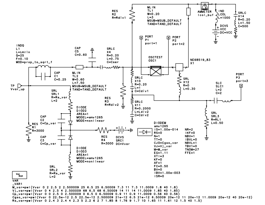
Modern set-top DBS TV tuners require high performance, broadband voltage control oscillator (VCO) designs at a competitive cost. To meet these goals, design engineers are challenged to create high performance, low-cost VCOs. Broadband voltage control oscillators (VCOs) are vital components...
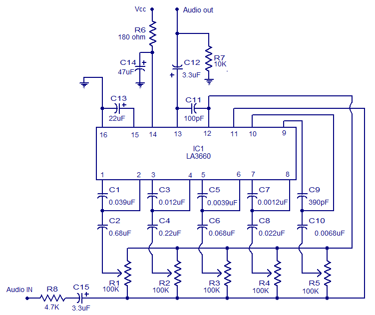
The graphic equalizer described is based on the LA3600 integrated circuit from Sanyo Semiconductors. The LA3600 is a single operational amplifier, 5-band graphic equalizer IC that is well-suited for applications such as portable stereo systems, radios, home theater systems,...
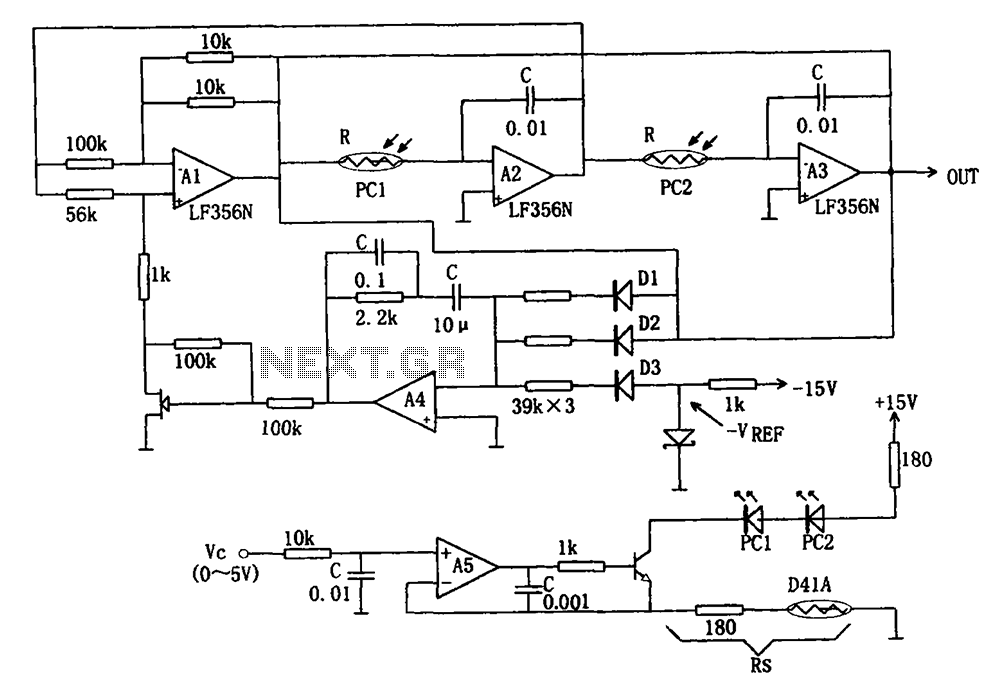
The wideband sinusoidal voltage-controlled oscillator circuit is designed such that the oscillation frequency is determined by an integrating resistor R and a capacitor C. The voltage-controlled oscillator is constituted by the applied control voltage Vc and a control resistor...
Warning: include(partials/cookie-banner.php): Failed to open stream: Permission denied in /var/www/html/nextgr/view-circuit.php on line 713
Warning: include(): Failed opening 'partials/cookie-banner.php' for inclusion (include_path='.:/usr/share/php') in /var/www/html/nextgr/view-circuit.php on line 713