
Broadband sine wave voltage controlled oscillator circuit diagram LF356N

The wideband sinusoidal voltage-controlled oscillator (VCO) circuit is a critical component in various electronic applications, particularly in communication systems and signal processing. The circuit's design relies on key components, including an integrating resistor (R) and a capacitor (C), which together define the oscillation frequency. The integration process allows for the generation of a sinusoidal waveform, making it suitable for wideband applications.
The control mechanism of the VCO is facilitated by the control voltage (Vc), which directly influences the oscillation frequency. The inclusion of variable resistors in conjunction with photocouplers (PC1 and PC2) enhances the circuit's adaptability to different operating conditions. Photocouplers provide electrical isolation and allow for control signals to modulate the VCO without direct electrical connections, improving safety and performance.
The rectifier circuit employed in the design operates in average detection mode, enabling the circuit to maintain a stable output despite variations in input signals. This characteristic is particularly advantageous when dealing with fluctuating control voltages or signal levels.
The operational amplifier (op-amp) 4559 plays a crucial role in maintaining a constant current for the light-emitting diode (LED) used in the optocoupler. This ensures that the optocoupler operates within its optimal parameters, providing reliable performance across varying conditions. The choice of resistor Rs for voltage-to-current conversion is flexible, allowing for customization based on the desired maximum control voltage (Vc) and current output (IFmax).
Overall, the wideband sinusoidal VCO circuit is a versatile and essential design, capable of delivering stable oscillation frequencies while accommodating a range of control inputs and operating conditions. Its careful selection of components and configuration ensures robust performance in various electronic applications. As shown for the wideband sinusoidal voltage controlled oscillator circuit. The circuit oscillation frequency is determined by integrating resistor R and a capacitor C, voltage -controlled oscillator is constituted by the applied voltage Vc control resistor R. Variable resistor circuit using photocoupler PC1 and PC2, rectifier circuit using the average detection mode. The actual operation of the circuit in the frequency of several tens of hertz. In addition, with respect to the control voltage Vc oscillation frequency depends on the characteristics of the circuit optocoupler used features.
Optocoupler light source is a light emitting diode driving current needs, therefore, using an op amp circuit 4559 constitute a constant current source circuit. Voltage/current conversion using Rs, the resistance Rs are free to choose the maximum control voltage Vc.
Circuit, IFmax 30mA, Vcmax 5V, the resistance Rs 180 .
Related Circuits
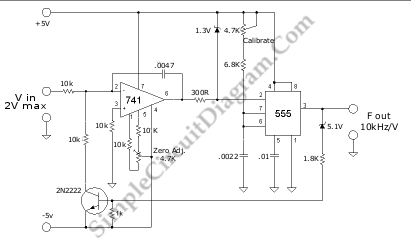
A voltage-to-frequency converter (VFC) circuit is illustrated in the schematic diagram below. The circuit utilizes a 555 integrated circuit (IC) as the central component of its operation. The voltage-to-frequency converter (VFC) is a crucial electronic circuit that converts an input...
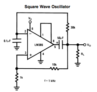
Here is a small LM386-based square-wave oscillator constructed from the following schematic. A 50k potentiometer was used in place of a 30k resistor, which functions as a pitch controller. The audio provided consists of track recordings made in Ableton...
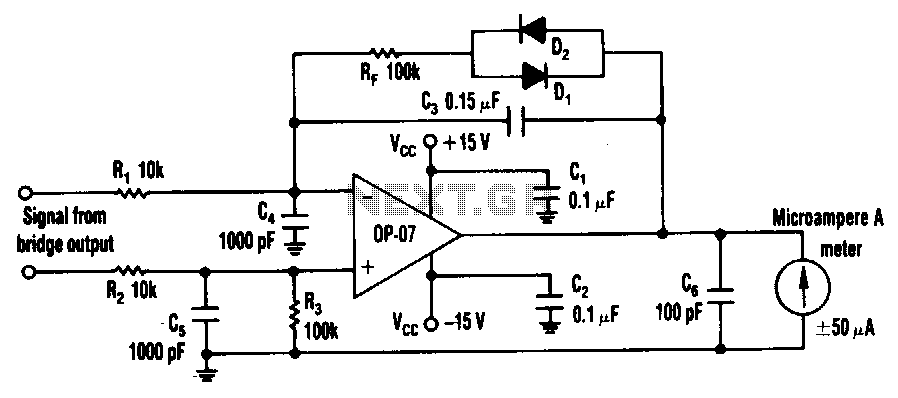
The circuit can utilize any general-purpose, low-offset, low-drift operational amplifier (op amp), such as the OP-07. The differential signal from the bridge feeds into an amplifier that drives a standard, rugged ±50 µA meter. However, near the null point,...
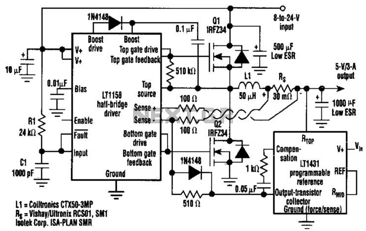
This regulator achieves 90% efficiency with a 12-V input and a 5-V output. It utilizes the LT1158 and LT1431 components from Linear Technology, Inc. High efficiency is accomplished by synchronously switching two power MOSFETs in a step-down switching regulator....
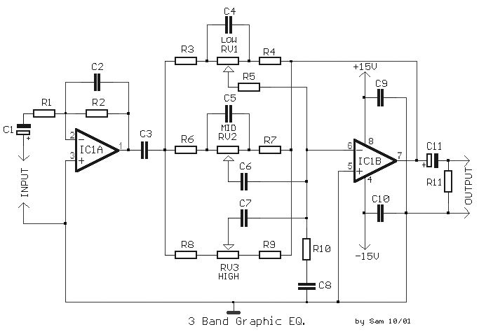
The circuit illustrates the use of three frequencies to produce a graphic equalizer that will be used for acoustic signals. The equalizer can be either passive or active. The graphic equalizer circuit operates by dividing the audio frequency spectrum into...
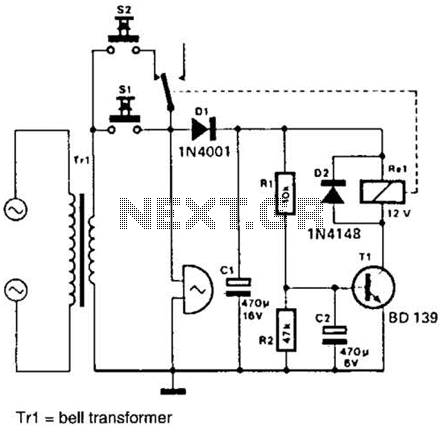
It is often desirable for a single doorbell to be operated by two buttons, for instance, one at the front door and the other at the back door. The additional button, S2 in series with the break contact of...