
7555 Light-sensitive Alarm
The circuit utilizes a light-dependent resistor (LDR) as the primary light sensor component. The LDR changes its resistance based on the amount of light falling on it; in bright conditions, its resistance is low, while in darkness, the resistance increases significantly. This change in resistance can be monitored using a voltage divider configuration, where the LDR is paired with a fixed resistor.
When a shadow is cast on the LDR, the resistance of the LDR increases, resulting in a voltage change at the output of the voltage divider. This output voltage can be fed into a comparator circuit, which compares it against a predefined threshold voltage. If the voltage drops below this threshold due to the shadow, the comparator output switches states, signaling a change.
To produce an audible alert, the output from the comparator can be connected to a transistor configured as a switch. When the comparator output goes high, it activates the transistor, allowing current to flow through a buzzer or piezo speaker, generating a sound. A capacitor may be included in the circuit to provide a brief delay in the buzzer activation, ensuring the alert is noticeable.
Additional components such as resistors and capacitors may be incorporated to stabilize the circuit and filter any noise, ensuring reliable operation. Power supply considerations should also be addressed, ensuring that the circuit operates within the specified voltage range for all components. The overall design should emphasize sensitivity to light changes while minimizing false positives from transient light variations.the function of this circuit for detects a sudden shadow falling on the light-sensor and sounds the bleeper when this happens. The light sensor is .. 🔗 External reference
Related Circuits
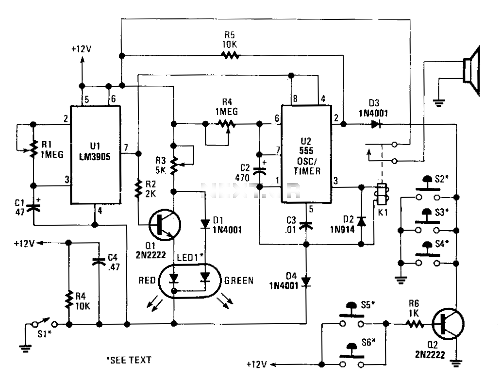
In operation, the alarm circuit allows a 0-47 second time delay, as determined by the R1/C1 combination, after the switch is armed to allow the vehicle's motion sensor to settle down. This provides time to retrieve items, such as...
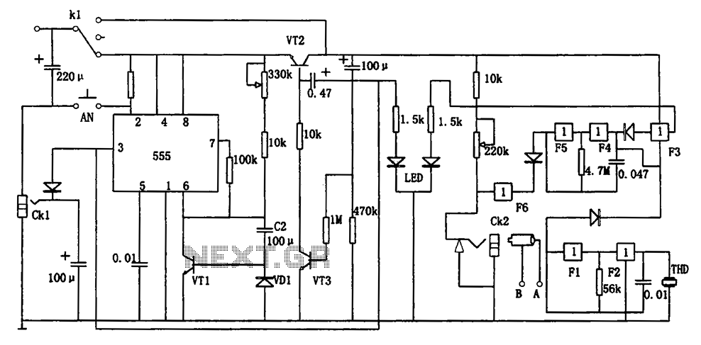
The circuit represents a general multi-function alarm and timing mechanism. Its timing capabilities range from 5 minutes to 3 hours. The timing components include C2, VD1, and VT1. The circuit utilizes a capacitance multiplier with a 555 timer. CK1,...
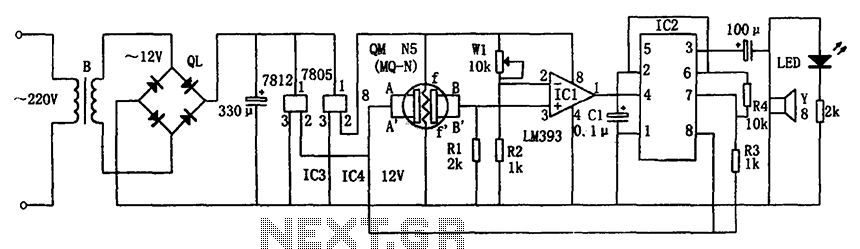
The circuit consists of a buck rectifier and voltage regulator, a gas sensor, a comparator circuit, and an alarm sound circuit. The buck regulator circuit includes a transformer, a bridge rectifier, and components such as QL, IC3 (7812), and...
Occasionally, a simple gated pulsed alarm is required. The circuit presented here utilizes only four components along with a piezo sounder, making it highly efficient in terms of simplicity. While it may not produce the most powerful output, it...
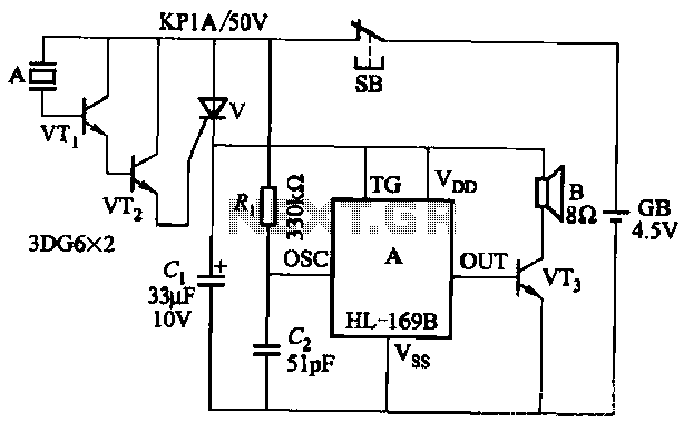
The circuit utilizes the HL-169B voice alarm integrated circuit (IC). It is designed for use in security applications, including glass doors, car doors, and windows, to act as a burglar alarm. When a thief applies force to these items,...
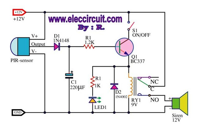
A motion detection alarm circuit utilizing a PIR sensor for motion detection. When movement is detected by the PIR sensor, it triggers a delay circuit, Q1, and other components. The motion detection alarm circuit is designed to provide an alert...
Warning: include(partials/cookie-banner.php): Failed to open stream: Permission denied in /var/www/html/nextgr/view-circuit.php on line 713
Warning: include(): Failed opening 'partials/cookie-banner.php' for inclusion (include_path='.:/usr/share/php') in /var/www/html/nextgr/view-circuit.php on line 713