
Gated Alarm
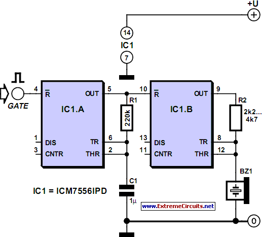
IC1.A functions as a slow oscillator that is activated when reset pin 4 is set to High and disabled when it is set to Low. The output pin 5 of IC1.A triggers the audio oscillator IC1.B, which is similarly enabled by setting reset pin 10 to High and disabled by setting it to Low. To simplify the operation of oscillator IC1.B, the piezo sounder X1 serves a dual purpose as both the timing capacitor and the sounder. This is feasible because a passive piezo sounder typically exhibits a capacitance in the range of several tens of nanofarads, although this value can vary significantly. As the capacitor-sounder charges and discharges, it emits a tone. The resistor R2 must be chosen to match the resonant frequency of the piezo sounder to achieve maximum volume. The circuit can operate on any supply voltage between 2 V and 18 V, with satisfactory output levels at higher supply voltages, provided that the voltage does not exceed 18 V.
The circuit design is straightforward and consists of minimal components, making it ideal for applications where simplicity and low power consumption are prioritized. The 7556 dual timer IC is central to the operation, providing the necessary timing functions for the oscillator configuration. The astable mode of operation allows for continuous oscillation, generating a square wave output that can be easily modified by adjusting the resistor values, particularly R2, to optimize the sound output from the piezo sounder.
The piezo sounder, acting as both a sound-producing element and a timing capacitor, simplifies the design and reduces the number of components required. This dual functionality is advantageous in compact designs where space is limited. The selection of the piezo sounder is critical, as its inherent capacitance influences the frequency of the generated tone. A careful choice of R2 in conjunction with the sounder’s characteristics will ensure the desired tonal output and volume level.
In terms of power supply considerations, the circuit's flexibility in operating voltage allows it to be integrated into various systems, from battery-operated devices to mains-powered applications, as long as the voltage remains within the specified range. The low supply voltage requirement enables the circuit to be energy-efficient, making it suitable for portable applications. Overall, this simple gated pulsed alarm circuit exemplifies an effective use of minimal components while providing essential functionality in various electronic projects.Sometimes the need arises for a simple, gated, pulsed alarm. The circuit shown here employs just four components and a piezo sounder and is unlikely to be out-done for simplicity. While it does not offer the most powerful output, it is likely to be adequate for many applications. A dual CMOS timer IC type 7556 is used for the purpose, with each of its two halves being wired as a simple astable oscillator (a standard 556 IC will not work in this circuit, nor will two standard 555`s). Note that the CMOS7556 is supplied by many different manufacturers, each using their own type code prefix and suffix.
The relevant Texas Instruments product, for instance, will be marked TLC556CN`. The circuit configuration used here is seldom seen, due probably to the inability of this oscillator to be more than lightly loaded without disturbing the timing. However, it is particularly useful for high impedance logic inputs, since it provides a simple means of obtaining a square wave with 1:1 mark-space ratio, which the orthodox` configuration does not so easily provide.
IC1. A is a slow oscillator which is enabled when reset pin 4 is taken High, and inhibited when it is taken Low. Output pin 5 of IC1. A pulses audio oscillator IC1. B, which is similarly enabled when reset pin 10 is taken High, and inhibited when it is taken Low. In order to simplify oscillator IC1. B, piezo sounder X1 doubles as both timing capacitor and sounder. This is possible because a passive piezo sounder typically has a capacitance of a few tens of nanofarads, although this may vary greatly.
As the capacitor-sounder charges and discharges, so a tone is emitted. The value of resistor R2 needs to be selected so as to find the resonant frequency of the piezo sounder, and with this its maximum volume. The circuit will operate off any supply voltage between 2 V and 18 V. A satisfactory output will be obtained at relatively high supply voltages, but do not exceed 18 V. 🔗 External reference
Related Circuits
The project was originally intended as a present for my brothers dorm room, but a bad capacitor and the lack of a proper oscilloscope caused delays. It has not made it off the breadboard, and it probably will not...
This is a straightforward 12V rechargeable smart battery charger circuit. It can be utilized as a charger for car batteries, inverter batteries, emergency light batteries, and more. An automatic indicator alarm circuit accompanies this battery charger schematic. The primary...
Connect this Alarm Phone Dialer to a device you wish to monitor, such as a high water alarm, low temperature alarm, back window, or garage door. When activated, it will call a series of pre-programmed numbers to notify you...

This circuit employs a thin piezoelectric sensor to detect vibrations caused by knocking on a surface, such as a door or table. It amplifies and processes the sensor's signal to trigger an alarm for a predetermined duration. The piezoelectric...

Removing R1 or R2 from the circuit allows a potential thief to break a hidden wire that connects R1 to +12 V and R2 to ground. This action activates the alarm for approximately five minutes. The circuit in question is...
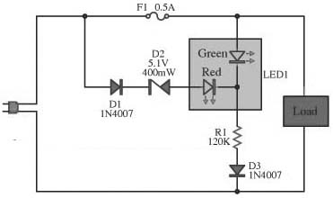
This circuit is designed to monitor the performance of the equipment. It includes a fuse check feature. The circuit is compact and can operate with various power supply voltages. It utilizes a two-color LED, which is of the common...