
PIR. motion sensor alarm circuit

The motion detection alarm circuit is designed to provide an alert in response to detected motion. The core component of this circuit is the Passive Infrared (PIR) sensor, which detects changes in infrared radiation, typically emitted by human bodies or animals. When the PIR sensor identifies movement within its range, it generates a high output signal.
The output from the PIR sensor is then fed into a delay circuit, which is often implemented using a transistor (Q1). The purpose of the delay circuit is to prevent false alarms caused by transient movements or environmental changes, such as passing cars or animals. This delay allows the circuit to filter out brief disturbances and only trigger the alarm for sustained movements.
In addition to the PIR sensor and the delay circuit, the alarm system may include other components such as resistors, capacitors, and possibly additional transistors or integrated circuits to amplify the signal or drive an output device, such as a buzzer or LED indicator. The output can be configured to activate an alarm system, alerting users to the presence of motion in the monitored area.
Power supply considerations must also be addressed, with the circuit typically designed to operate on a low voltage, often sourced from batteries or a regulated power supply. The overall design should ensure low power consumption to extend the operational life of battery-powered applications.
This motion detection alarm circuit can be utilized in various applications, including home security systems, automated lighting control, and smart home integrations, providing an effective solution for monitoring and alerting users to movement.A motion detection alarm circuit using a PIR.SENSOR motion detection, if the move is a positive light from the PIR sensor, triggered by a delay circuit, Q1 and.. 🔗 External reference
Related Circuits

When the protective circuit is interrupted (opened), the alarm sounds. To set the circuit, adjust R2 (with the protective circuit open) for 1 V across R1. The described circuit functions as a protective alarm system that activates when the integrity...
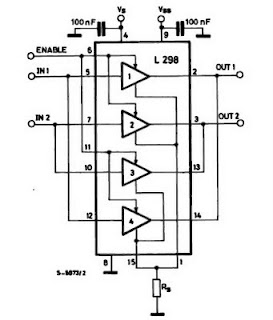
The IC H-Bridge DC motor driver L298 contains two H-Bridge circuits, allowing it to drive two DC motors simultaneously. Each H-Bridge circuit can deliver currents up to 2A. When used in parallel, the L298 can provide a total current...
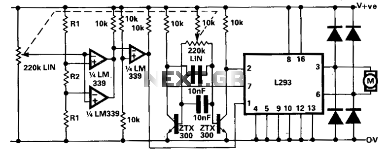
A limitation of the bi-directional proportional motor control circuit is that when the potentiometer is in its center position, the motor does not stop but continues to creep. This occurs due to the challenge of precisely adjusting the potentiometer...
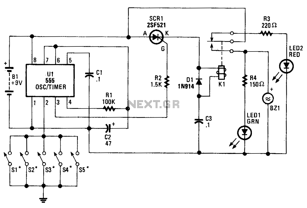
The core component of the circuit is a 555 timer/oscillator, designated as U1, which is configured for monostable operation. The output from U1 at pin 3 is connected to the gate of SCR1. As long as switches S1 to...
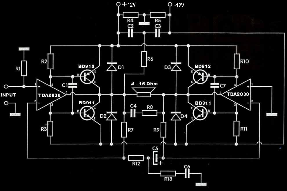
The TDA2030 amplifier circuit is suitable for driving low-frequency subwoofer speakers in home theater systems. The TDA2030 is a monolithic integrated circuit designed for use as a low-frequency class AB amplifier. This TDA2030 amplifier design requires a dual power...
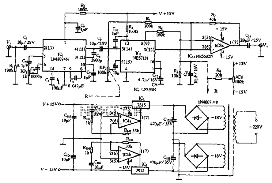
The NE571 and LM1894N form a dynamic expander circuit that enhances performance. This dynamic expander utilizes a variable bandpass filter with the LM1894N. It is particularly effective for dynamic expansion, requiring an RMS rectifier to mitigate noise modulation effects,...