
7W Mini Audio Amplifier Circuit based LM383
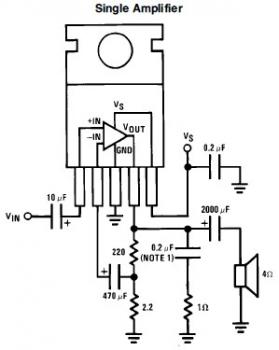
The mini audio amplifier circuit utilizing the LM383 is designed for simplicity and effectiveness in audio signal amplification. The LM383 is a power amplifier IC that offers high performance with minimal external components. The circuit configuration typically includes the LM383 connected to a suitable power supply, in this case, a 9V battery, which provides the necessary voltage for operation. The design may incorporate a few discrete components, such as resistors, capacitors, and inductors, to ensure stability and performance.
To further enhance the performance and prevent unwanted oscillations, the inclusion of a low-value inductor at the input stage is crucial. This inductor serves to filter high-frequency noise that may otherwise interfere with the audio signal. Furthermore, the output stage benefits from the addition of a 0.2µF capacitor in series with a 1-ohm resistor, which acts as a damping mechanism to stabilize the output and reduce the risk of oscillation, especially under varying load conditions.
The audio amplifier's primary function is to boost low-level audio signals from various sources, such as MP3 players, to a level that can effectively drive loudspeakers. This amplification is essential for achieving a satisfactory listening experience, as it allows the audio signals to be heard clearly and at higher volumes. The circuit's design ensures that it can handle the frequency range critical for human hearing, providing a well-rounded audio output.
In terms of construction, the choice of a PCB for assembly is recommended due to its reliability and ease of soldering components in a compact layout. However, for those who prefer a more hands-on approach, a perf board can also be utilized, albeit with careful attention to the layout to avoid noise and interference.
Overall, the mini audio amplifier circuit based on the LM383 is an excellent project for those interested in audio electronics, offering a practical solution for amplifying audio signals with minimal complexity.This is a very-very simple mini audio amplifier circuit. The circuit build based single LM383 with several discrete circuit to support LM383. The circuit capable to deliver about 7W audio output. The circuit could be built on a perf board, universal solder board or PC board, the PC board is preferred. I built the circuit on a perf board and had t o add a low value inductor at the input to stop oscillation. In the event you add a 0. 2uF capaciitor in series with a 1 ohm resistor to the output you`ll be able to prevent oscillation of the circuit under specific conditions. An audio amplifier is an electronic amplifier that amplifies low-power audio signals (signals composed primarily of frequencies between 20 - 20 000 Hz, the human range of hearing) to a level suitable for driving loudspeakers and is the final stage in a typical audio playback chain.
The preceding stages in such a chain are low power audio amplifiers which perform tasks like pre-amplification, equalization, tone control, mixing/effects, or audio sources like record players, CD players, and cassette players. Most audio amplifiers require these low-level inputs to adhere to line levels. While the input signal to an audio amplifier may measure only a few hundred microwatts, its output may be tens, hundreds, or thousands of watts.
More explanation about power audio amplifier can be found at wikipedia. org This is the video tutorial about how to build a realy simple headphone amplifier. The circuit powered with 9V battery and use an IC to amplify the input signal from mp3 player. 🔗 External reference
Related Circuits
A very popular circuit for driving DC motors (ordinary or gearhead) is called an H-bridge. It's called that because it looks like the capital letter 'H' on classic schematics. The great ability of an H-bridge circuit is that the...
The LM4844 is an integrated audio subsystem designed for stereo cell phone applications. Operating on a 3.3V supply, it combines a stereo speaker amplifier delivering 495mW per channel into an 8Ω load and a stereo OCL headphone amplifier delivering...
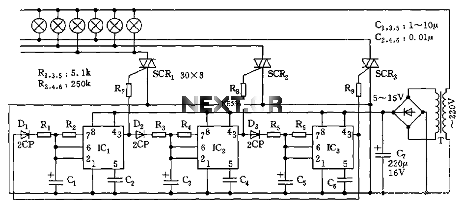
The circuit utilizes a 555 timer as its core component to control three lights through a cyclic trigger monostable delay circuit. The brightest light is controlled by a silicon-controlled rectifier (SCR) that determines the cycle of illumination. When pin...
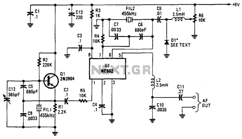
Q1 is a fixed oscillator operating at 455 kHz. U1 is a mixer with its own internal oscillator running at 45.5 kHz. FIL1 and FIL2 are Murata CSB455E filters or equivalent. D1 is a varactor diode (an IN4002 used...
The circuit was designed to create a line preamplifier using double triode tubes. It consists of three parts, including the main preamplifier. The line preamplifier circuit utilizing double triode tubes is structured to enhance audio signals by amplifying low-level signals...
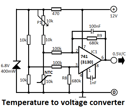
This simple temperature-to-voltage converter circuit allows for precise measurement of room temperature using an NTC resistor or thermistor. The temperature-to-voltage converter circuit typically employs a negative temperature coefficient (NTC) thermistor, which exhibits a decrease in resistance as temperature increases. This...
Warning: include(partials/cookie-banner.php): Failed to open stream: Permission denied in /var/www/html/nextgr/view-circuit.php on line 713
Warning: include(): Failed opening 'partials/cookie-banner.php' for inclusion (include_path='.:/usr/share/php') in /var/www/html/nextgr/view-circuit.php on line 713