
Line Preamplifier Circuit with Tube Acquisition

The line preamplifier circuit utilizing double triode tubes is structured to enhance audio signals by amplifying low-level signals before they are processed by further audio equipment. The design typically includes three primary sections: the input stage, the amplification stage, and the output stage.
The input stage is responsible for receiving the audio signal, which is often weak and needs to be amplified. It may include coupling capacitors to block any DC offset and allow only the AC audio signal to pass through. The use of double triode tubes in this stage provides high input impedance, ensuring minimal loading on the source device, which is crucial for maintaining signal integrity.
The amplification stage is where the primary signal boosting occurs. The double triode tubes function as voltage amplifiers, utilizing their characteristics to provide significant gain while maintaining linearity. Biasing resistors are employed to set the operating point of the tubes, ensuring they function within their optimal range. Feedback mechanisms may also be integrated to stabilize gain and reduce distortion, enhancing overall audio quality.
Finally, the output stage is designed to deliver the amplified signal to the next stage in the audio chain, such as a power amplifier or audio processor. Output transformers may be used to match the impedance of the preamplifier with that of the subsequent stage, ensuring efficient signal transfer and minimizing signal loss.
Overall, the circuit is engineered to provide high-fidelity audio amplification, leveraging the unique properties of double triode tubes to achieve a warm and rich sound characteristic, often preferred in high-end audio applications. Proper attention to component selection, layout, and power supply design is essential to optimize performance and reliability in the final implementation.The circuit was designed to create a line preamplifier by acquiring the use of double triode tubes. The circuit comprises of three parts, the main preampl.. 🔗 External reference
Related Circuits
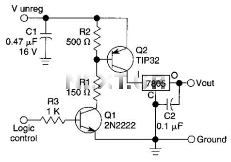
A logic level can control a 7805 regulator with this circuit. Q2 is a series switching transistor controlled by Q1. Q1 is turned on by a logic voltage to its base. This circuit utilizes a 7805 voltage regulator, which is...
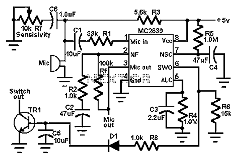
The circuit schematic utilizes the MC2830 voice circuit. Traditional voice circuits are unable to differentiate between speech and noise in the input signal. In noisy environments, such as those caused by switches, this limitation is significant. To address this...
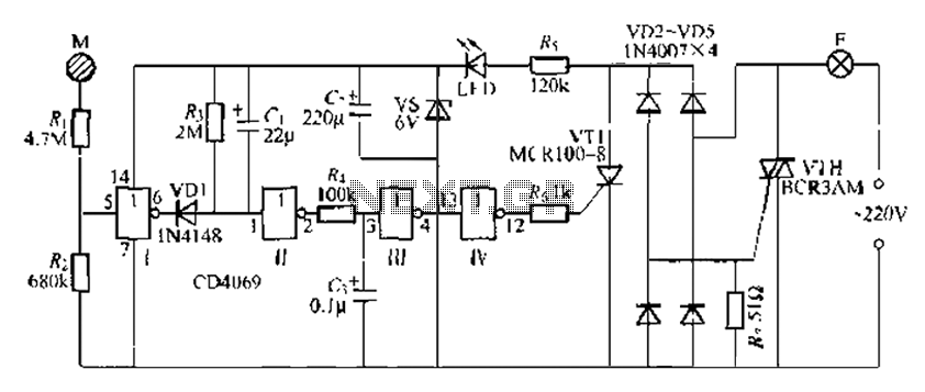
The CD4069 is a digital integrated circuit that utilizes boron to delay the activation of a light touch. It employs a j-wire connection force method and can directly replace a standard light switch without requiring changes to the existing...
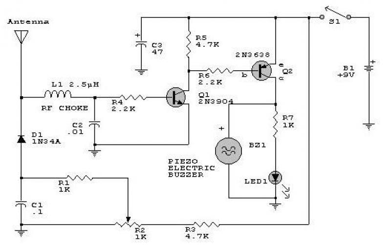
This circuit responds to RF signals below the standard broadcast band up to over 500 MHz and provides both visual and audible indications when an RF signal is detected. By adjusting the bias of diode D2 with the R2...
CMOS interface circuit with PMOS cross-coupled PMOS integrated circuit featuring high input impedance, where the input current can be ignored. The CMOS and PMOS interface circuit is illustrated in the accompanying figure. The CMOS interface circuit utilizing PMOS cross-coupled configurations...
Old TV tubes are used as cold cathode x-ray emitters in a simple apparatus developed by Bob Templeman of Chicago, Illinois. With selected beam power tubes of the type used in the high voltage section of TV receivers, the...