
Temperature to Voltage Converter Circuit

The temperature-to-voltage converter circuit typically employs a negative temperature coefficient (NTC) thermistor, which exhibits a decrease in resistance as temperature increases. This property makes it suitable for temperature sensing applications. The circuit can be designed using an operational amplifier (op-amp) to convert the resistance change of the thermistor into a corresponding voltage output.
In a basic configuration, the thermistor is connected in a voltage divider arrangement with a fixed resistor. The output voltage from this divider is then fed into the non-inverting input of the op-amp. The op-amp can be configured in a non-inverting amplifier mode, where it amplifies the voltage signal from the thermistor. The gain of the op-amp can be adjusted by selecting appropriate feedback and input resistors.
To enhance the accuracy of the temperature measurement, the circuit may include calibration adjustments. This can be achieved by incorporating a potentiometer in the feedback loop of the op-amp, allowing for fine-tuning of the output voltage to match known temperature values.
The output voltage from the op-amp can be interfaced with an analog-to-digital converter (ADC) for digital temperature readings, or it can be used to drive an analog display such as an LED or an analog meter. The entire circuit can be powered using a standard DC power supply, ensuring stable operation across a range of environmental conditions.
In summary, the temperature-to-voltage converter circuit utilizing an NTC thermistor and an op-amp provides a reliable method for measuring room temperature, with potential applications in HVAC systems, environmental monitoring, and home automation.With this simple temperature to voltage converter circuit we can do a precise measurement of the temperature in a room. A NTC resistor or a thermistor is u.. 🔗 External reference
Related Circuits

This schematic is directly sourced from the Altera ByteBlaster datasheet or manual, which provides comprehensive details regarding the connector's functionality and pin connections. It is advisable to review the datasheet available on their website or through a search engine...
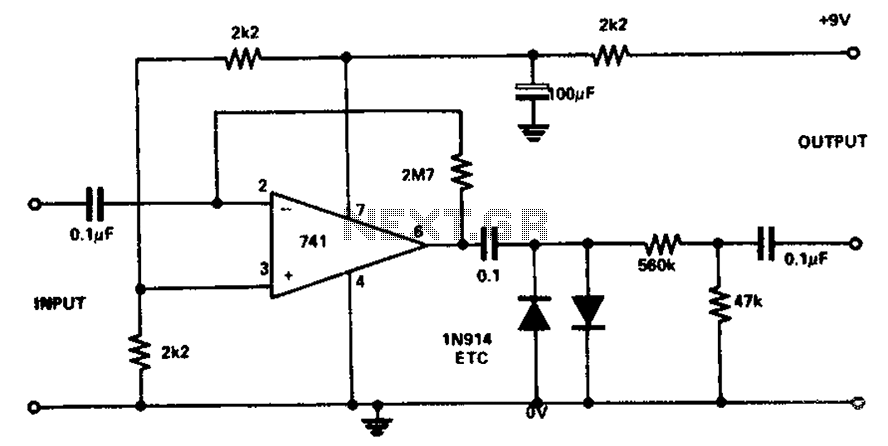
The circuit utilizes the 741 operational amplifier, which has a maximum gain of 20,000. However, the design achieves a gain of 2.7 million, resulting in output distortion. This distortion is attributed to noise effects. Two clamping diodes are employed...
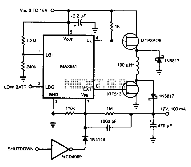
This converter can accommodate wide input voltage swings, such as the 8 to 15 V range typical of a 12 V sealed lead-acid battery. The low battery output indicates when the input voltage drops below 8 V. Pulling the...
This is an aerial current power supply with a continuously adjustable stabilized output ranging from 0 to 30VDC. The circuit also incorporates an electronic current limiter that effectively controls the output current from a few milliamperes (2 mA) to...
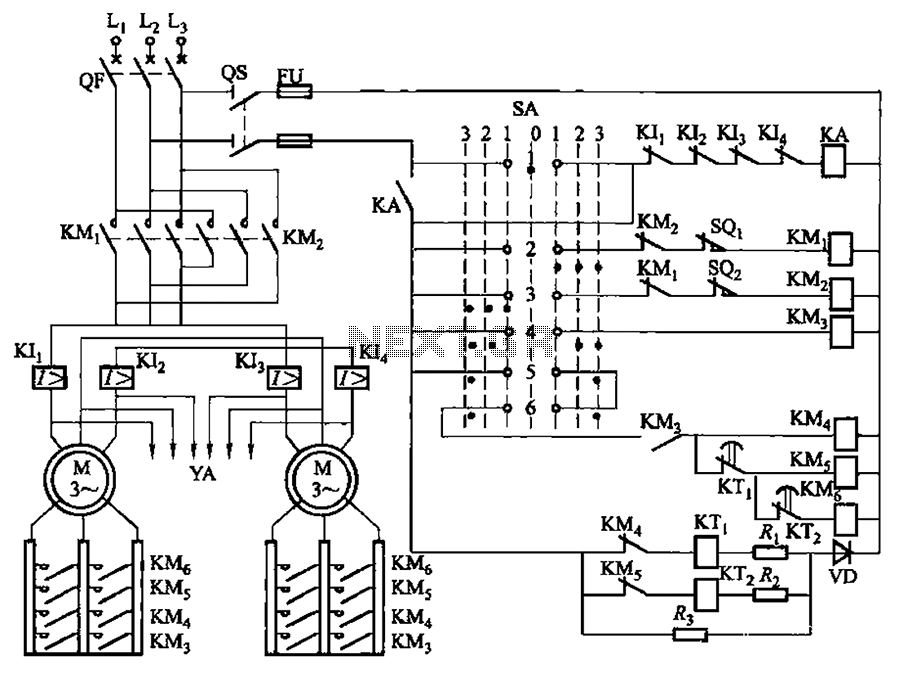
The LK16-5/31 type master controller and PQY2 Series Magnetic control panel comprise a control circuit. The PQY2 series control panel, along with the magnetic PQY1 control panel, features a similar control circuit. The electrical components are fundamentally the same;...
It utilizes the mains supply through a basic DC rectifier circuit. The circuit operates by converting alternating current (AC) from the mains supply into direct current (DC) using a rectifier. A typical implementation involves a bridge rectifier configuration, which consists...