
800 W SOFT START LIGHT DIMMER
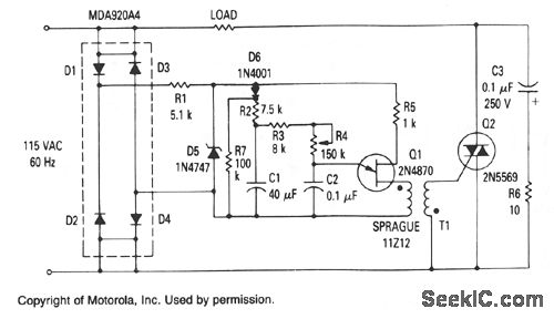
The circuit utilizes a Zener diode to maintain a steady voltage of 20 V, which is crucial for the operation of the unijunction transistor (Q1). This configuration is particularly effective in applications where consistent voltage regulation is required, such as in lamp dimming circuits. The unijunction transistor serves as a triggering device, which is activated by the charge stored in capacitors C1 and C2.
Initially, capacitor C1 has no charge, leading to an inability for capacitor C2 to reach the necessary voltage to trigger Q1. As the input voltage rises during the half-cycle, C1 begins to charge, albeit slowly due to the low voltage conditions. This results in a delayed triggering of Q1, which occurs only at the latter part of the half-cycle. The gradual increase in voltage allows for a controlled rise in current through the lamp, preventing excessive inrush current which could otherwise damage the lamp.
The design incorporates a resistor (R4) in series with capacitor C2, which plays a dual role: it regulates the charging rate of C2 and facilitates lamp dimming by adjusting the time constant of the charging circuit. This allows for fine-tuning of the lamp's brightness according to the desired application. Additionally, the inclusion of diode D6 and resistor R7 enhances the circuit's performance by improving its behavior at low conduction angles, ensuring stable operation even under varying load conditions.
Overall, this circuit design effectively balances the need for voltage regulation, controlled current flow, and dimming capabilities, making it suitable for various lighting applications. The careful selection of components and their arrangement contributes to the reliability and efficiency of the system.The zener provides a constant voltage of 20 V to unijunction transistor Q1, except at the end of each half-cycle of the input when the line voltage drops to zero. Initially, the voltage across capacitor C1 is zero and capacitor C2 cannot charge to trigger Q1. C1 will begin to charge, but because the voltage is low, C2 will be charged to a voltage adequate to trigger C1 only near the end of the half cycle. Although the lamp resistance is low at this time, the voltage applied to the lamp is low and the inrush current is small. Then the voltage on C1 rises, allowing C2 to trigger Q1 earlier in the cycle. At the same time, the lamp is being heated by the slowly increasing applied voltage. By the time the peak voltage applied to the lamp has reached its maximum value, the bulb has been heated sufficiently to keep the peak inrush current at a reasonable value.
Resistor R4 controls the charging rate of C2 and provides the means to dim the lamp. Diode D6 and resistor R7 improve operation at low-conduction angles. 🔗 External reference
Related Circuits
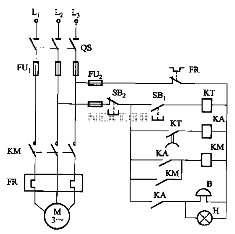
The circuit shown in Figure 3-21 is designed to produce a motor startup sound and a light signal indicating the completion of the startup process, after which the signal ceases. This circuit is tailored to control the motor for...
ESP Lighting Information Page - Dimmers, electronic transformers, etc. - how they work, what is wrong with them, and how it can be fixed. The ESP Lighting Information Page provides insights into various lighting components, specifically focusing on dimmers and...
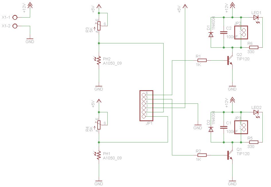
The figures above illustrate the fundamental concept of a robot, which comprises input and output devices connected to a central processing unit, often referred to as the brain. In this case, the Arduino acts as the brain, controlling all...
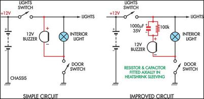
Two headlight reminder circuits are simple to install and operate based on the KISS (Keep It Simple Stupid) principle. The basic circuit consists of a 12V piezo buzzer connected between the lights circuit and a door switch. The buzzer...
The success or failure of lighting upgrades depends on the quality of components and workmanship. Proper wire routing is essential to prevent insulation chafing. The quality of soldering connections is crucial, as poor solder joints can corrode and fail....
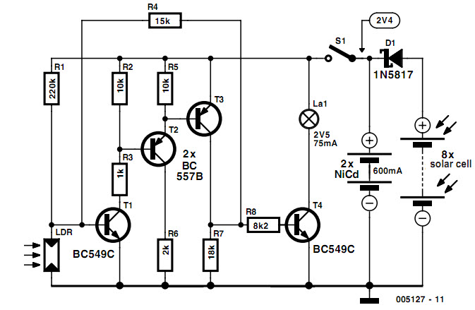
Completely self-supporting garden lamps that utilize solar cells as their energy source are becoming increasingly common. These lamps operate by harnessing sunlight, which is freely available during the day, to provide the necessary energy for illumination during the evening....
Warning: include(partials/cookie-banner.php): Failed to open stream: Permission denied in /var/www/html/nextgr/view-circuit.php on line 713
Warning: include(): Failed opening 'partials/cookie-banner.php' for inclusion (include_path='.:/usr/share/php') in /var/www/html/nextgr/view-circuit.php on line 713