
Lighting Consultancy and Supply
The design of a headlamp circuit must prioritize both safety and performance. The wiring should be robust enough to handle the current demands of modern headlamps, which may require larger gauge wires to minimize resistive losses. A common approach involves running a dedicated power line directly from the battery to the headlamps, bypassing the factory switch. This setup often includes a relay that is activated by the original headlamp switch, allowing for a higher current to flow directly to the bulbs while maintaining the factory control functionality.
The relay should be rated for the appropriate load and placed in a location that is protected from moisture and road debris. The use of weatherproof connectors and heat-shrink tubing for soldered joints can enhance the durability of the connections. Additionally, the installation of fuses near the battery will provide protection against short circuits, further safeguarding the vehicle's electrical system.
In terms of wire selection, using 12 or 14 gauge stranded wire for the power feed to the headlamps is advisable to ensure minimal voltage drop and adequate current handling. The ground connections should also be robust, with a direct path back to the vehicle chassis to ensure efficient operation of the headlamps.
When upgrading headlamps, it is critical to consider the optical characteristics of the bulbs being used. While higher wattage bulbs can provide increased brightness, they may also produce excess heat, potentially damaging the headlamp housing or wiring. Therefore, it is essential to select bulbs that are compatible with the existing headlamp assemblies and to verify that the vehicle's electrical system can handle the additional load without exceeding the limits of the wiring and fuses.
Finally, regular inspections of the headlamp circuit should be conducted to ensure that all connections are secure and free of corrosion. This proactive maintenance will help to ensure consistent performance and safety while driving, especially during nighttime or adverse weather conditions.The success or failure of your lighting upgrade efforts rides on the quality of your parts and the quality of your work. It matters how carefully you route wires to avoid chafing insulation. It matters how well you solder connections (crimps and sloppy or `cold` solder joints corrode and die).
It matters how well you shield added wiring from road spray. It matters that you use fuses in the new wiring to protect against vehicle damage due to a new or old electrical fault. It matters that you use high-quality parts that are designed to stand up to the rigors of automotive usage.
Such components must be resistant to a wide range of temperatures, road splash, fumes found under the hood of every car, severe and prolonged vibration, etc. It will pay you to select only the products of companies with well established reputations for quality and durability; your $2.
25 bargain no-name relay could easily kill you when it fails on a dark road somewhere, leaving you with no lights. Do not purchase vehicle components based solely on price! The techniques described in this article will yield excellent results only if the work is carried out carefully and to a high standard, with quality parts and materials and without corner-cutting or sloppy work.
I personally wouldn`t perform this upgrade on a really collectible car without taking care to hide all the new wiring. Actually, there`s probably not much need to go to high-powered Cibie (or other European-specification) headlamps on a true collector car that is not driven at night.
But on a hard-working daily (and nightly) driver like mine, powerful headlights are a real blessing, and keeping the wiring out in the open where it can be seen and inspected helps avoid failures! Also keep in mind that this article focusses on the general principle behind headlamp wiring. There are many variations in original-equipment headlamp circuit design, and it will be worth your while to examine your vehicle`s setup thoroughly, preferably with the aid of wiring diagrams applicable to your specific vehicle.
Power for the headlights is controlled by a switch on the dash. This is *not* a great place to tap into the system, for two reasons: The headlamp switch uses tiny, high-resistance contacts to complete circuits, and the wire lengths required to run from the battery to the dashboard and all the way out to the headlamps creates excessive resistive voltage drop, especially with the thin wires used in most factory installations. In many cases, the thin factory wires are inadequate even for the stock headlamp equipment. Headlamp bulb light output is severely compromised with decreased voltage. The drop in light output is not linear, it is exponential with the power 3. 4. For example, let`s consider a 9006 low beam bulb rated 1000 lumens at 12. 8 Volts and plug in different voltages: The Europeans take a slightly more realistic with their voltage ratings; they consider output at 13.
2v to be "100%". The loss curve is the same, though. When operating voltage drops to 95 percent (12. 54v), headlamp bulbs produce only 83 percent of their rated light output. When voltage drops to 90 percent (11. 88v), bulb output is only 67 percent of what it should be. And when voltage drops to 85 percent (11. 22v), bulb output is a paltry 53 percent of normal! It is much more common than you might think for factory headlamp wiring/switch setups to produce this kind of voltage drop, especially once they`re no longer brand new and the connections have accumulated some corrosion and dirt. From the headlamp on-off switch, a single wire runs to the beam selector (high/low) switch. Two wires run from the dimmer to the front of the car: one for high beams, one for low. Those are long lengths of thin wire between the battery and the headlamps! Typically we find 16 gauge wire (1. 5 mm2) at best, more commonly 18 gauge (1. 0 mm2) and in some cases even 20 gauge (0. 5 mm2). Most s 🔗 External reference
Related Circuits
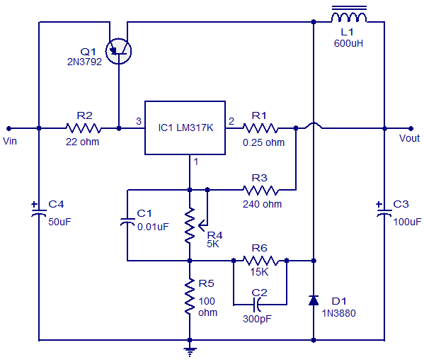
This circuit illustrates a 3A Switching Regulator Circuit based on the LM317K integrated circuit. It is designed to be simple and cost-effective. The 3A Switching Regulator Circuit utilizing the LM317K IC serves as a versatile voltage regulation solution, capable of...
This dual polarity power supply is simple to construct, requires minimal components, and is adjustable from 0 to 15 volts. It is suitable for powering operational amplifier circuits as well as other circuits that necessitate a dual supply voltage....
This project uses the 1.2v rechargeable battery and solar panel from a Solar Garden Light. These lights can be bought for less than $5.00 in most $2.00 shops or similar shops that sell general household items. We are also...
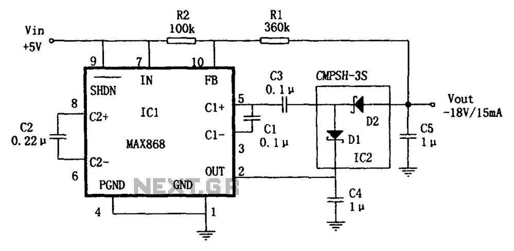
The circuit utilizes the IC1 MAX868 and CMPSH-3S to create a quadruple voltage DC/DC converter power supply. The IC1 MAX868 is an inverting charge pump regulator integrated circuit that can generate an output voltage of up to -2VIN, with...
A Variable DC Power Supply is one of the most useful tools on the electronics hobbyist's workbench. This circuit is not an absolute novelty, but it is simple, reliable, rugged, and short-proof, featuring variable voltage up to 24V and...
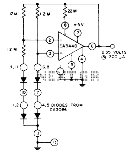
The circuit utilizes a CA3440 BiMOS operational amplifier and a CA3086 transistor array. The no-load current drawn from the 5-volt supply is 1.5 µA. The load current can reach up to 200 µA while still maintaining output voltage regulation...
Warning: include(partials/cookie-banner.php): Failed to open stream: Permission denied in /var/www/html/nextgr/view-circuit.php on line 713
Warning: include(): Failed opening 'partials/cookie-banner.php' for inclusion (include_path='.:/usr/share/php') in /var/www/html/nextgr/view-circuit.php on line 713