
80mW Audio Amplifier
More: This circuit corrects the problem somewhat and allows a larger voltage swing and probably more output power, but I don't know how much without doing a lot of testing. The output still won't move more than a couple volts using small transistors since the peak current won't be more than 100mA or so into a 25 ohm load. But it's an improvement over the other circuit above.
In this circuit, the 1K load resistor is tied to the speaker so that as the output moves negative, the voltage on the 1K resistor is reduced, which aids in turning off the top NPN transistor. When the output moves positive, the charge on the 470uF capacitor aids in turning on the top NPN transistor.
The original circuit in the radio used a 300 ohm resistor where the 2 diodes are shown but I changed the resistor to 2 diodes so the amp would operate on lower voltages with less distortion. The transistors shown 2n3053 and 2n2905 are just parts I used for the other circuit above and could be smaller types. Most any small transistors can be used, but they should be capable of 100mA or more current. A 2N3904 or 2N3906 are probably a little small, but would work at low volume.
The 2 diodes generate a fairly constant bias voltage as the battery drains and reduces crossover distortion. But you should take care to ensure the idle current is around 10 to 20 milliamps with no signal and the output transistors do not get hot under load.
The circuit should work with a regular 8 ohm speaker, but the output power may be somewhat less. To optimize the operation, select a resistor where the 100K is shown to set the output voltage at 1/2 the supply voltage (4.5 volts). This resistor might be anything from 50K to 700K depending on the gain of the transistor used where the 3904 is shown.
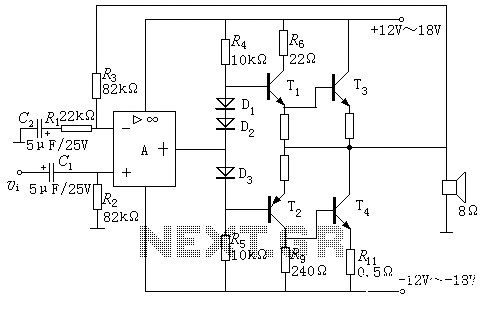
The circuit employs a positive feedback mechanism to enhance the amplitude of the output signal delivered to the speaker. The design incorporates a 25-ohm speaker, compatible with the output capabilities of the circuit. A critical component of the design is the load resistor for the driver transistor, which is connected directly to the positive supply. This arrangement can lead to limitations in output voltage swing due to the reduction in base current as the output voltage increases, which is mitigated in this revised circuit design.
The circuit features a 1K load resistor connected to the speaker, which plays a pivotal role in managing the output transistor's behavior. As the output voltage transitions to a negative state, the voltage drop across the 1K resistor decreases, thereby assisting in the deactivation of the top NPN transistor. Conversely, when the output voltage swings positive, the charge stored in the 470µF capacitor provides additional base current to turn on the NPN transistor, allowing for greater output voltage swing and power.
The original radio circuit utilized a 300-ohm resistor in place of the two diodes that have been adopted in this design. The substitution of diodes serves to lower the operating voltage range and minimize distortion, enhancing the overall performance of the amplifier. While the transistors specified (2N3053 and 2N2905) are suitable for this application, smaller transistors capable of handling at least 100mA can also be employed. For instance, transistors like the 2N3904 or 2N3906 may suffice for low-volume applications.
The dual diodes in the circuit provide a stable bias voltage, which is essential for maintaining consistent performance as the power supply voltage decreases over time. Crossover distortion is effectively reduced through this biasing scheme. It is recommended to maintain an idle current of approximately 10 to 20 milliamps when no audio signal is present to ensure that the output transistors remain cool during operation.
Although the circuit is compatible with standard 8-ohm speakers, the output power may be reduced in this configuration. To optimize performance, it is advisable to select a resistor value for the 100K resistor position that establishes the output voltage at half the supply voltage (approximately 4.5 volts). The optimal resistor value can vary between 50K and 700K, depending on the gain characteristics of the selected transistor.This circuit is similar to the one above but uses positive feedback to get a little more amplitude to the speaker. I copied it from a small 5 transistor radio that uses a 25 ohm speaker. In the circuit above, the load resistor for the driver transistor is tied directly to the + supply. This has a disadvantage in that as the output moves positive, the drop across the 470 ohm resistor decreases which reduces the base current to the top NPN transistor.
Thus the output cannot move all the way to the + supply because there wouldn't be any voltage across the 470 resistor and no base current to the NPN transistor. This circuit corrects the problem somewhat and allows a larger voltage swing and probably more output power, but I don't know how much without doing a lot of testing. The output still won't move more than a couple volts using small transistors since the peak current won't be more than 100mA or so into a 25 ohm load.
But it's an improvement over the other circuit above. In this circuit, the 1K load resistor is tied to the speaker so that as the output moves negative, the voltage on the 1K resistor is reduced, which aids in turning off the top NPN transistor. When the output moves positive, the charge on the 470uF capacitor aids in turning on the top NPN transistor.
The original circuit in the radio used a 300 ohm resistor where the 2 diodes are shown but I changed the resistor to 2 diodes so the amp would operate on lower voltages with less distortion. The transistors shown 2n3053 and 2n2905 are just parts I used for the other circuit above and could be smaller types.
Most any small transistors can be used, but they should be capable of 100mA or more current. A 2N3904 or 2N3906 are probably a little small, but would work at low volume. The 2 diodes generate a fairly constant bias voltage as the battery drains and reduces crossover distortion. But you should take care to insure the idle current is around 10 to 20 milliamps with no signal and the output transistors do not get hot under load.
The circuit should work with a regular 8 ohm speaker, but the output power may be somewhat less. To optimize the operation, select a resistor where the 100K is shown to set the output voltage at 1/2 the supply voltage (4.5 volts). This resistor might be anything from 50K to 700K depending on the gain of the transistor used where the 3904 is shown.
🔗 External reference
Related Circuits
This amp delivers a lot of power and uses 1 IC and two power transistors. The circuit consists of an amplifier IC (a TDA 2030A) and a power stage consists of two transistors. The amplifier can be powered with...
Many designers assert that NFB loop controlled amplifiers are inferior because they degrade the sound. However, it's worth considering what these individuals believe they are actually listening to. The reality is that most vinyl waveforms and CD pits, as part...
In a power supply circuit with a rating of 15V and a 10W power load, there are notable differences between two circuit configurations. The first configuration (A) uses discrete components in place of an integrated operational amplifier for the...
The Wien-Bridge oscillator meets specific requirements due to the presence of a low-pass filter, a high-pass filter, and a 180-degree phase shift from the feedback networks connecting the input to the output. This configuration results in a total phase...
Both halves of the circuit are identical. Both inputs have a DC path to ground via the input 47k control, which should be a dual logarithmic type potentiometer. The balance control is a single 47k linear potentiometer, which, when...
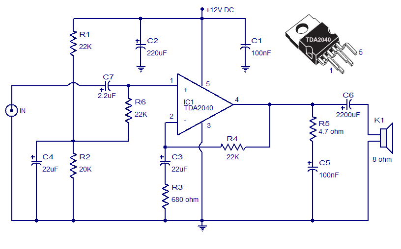
The Car Stereo Amplifier Circuit featuring the TDA2040 is presented here. The TDA2040 is a monolithic integrated audio amplifier that operates in Class AB mode. This integrated circuit includes built-in short circuit protection and thermal management features, allowing it...
Warning: include(partials/cookie-banner.php): Failed to open stream: Permission denied in /var/www/html/nextgr/view-circuit.php on line 713
Warning: include(): Failed opening 'partials/cookie-banner.php' for inclusion (include_path='.:/usr/share/php') in /var/www/html/nextgr/view-circuit.php on line 713