
877 ~ 924MHz RF2152 power amplifier the circuit diagram
The RF2152 is a high-performance power amplifier designed for applications in the 877 to 924 MHz frequency range. This amplifier is typically used in various RF communication systems, including wireless networks and mobile communication devices.
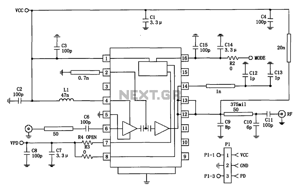
The circuit diagram of the RF2152 power amplifier includes several key components to ensure efficient operation and signal integrity. The amplifier is typically powered by a suitable DC voltage source, which is connected to the Vcc pin. The device is designed to provide a significant gain while maintaining linearity, which is crucial for minimizing distortion in the transmitted signal.
Input matching networks are often employed at the input stage to optimize the impedance seen by the RF signal source, enhancing the power transfer to the amplifier. These matching networks may consist of inductors and capacitors configured to resonate at the desired frequency.
The output stage of the RF2152 includes a load matching network to ensure that the output impedance is compatible with the subsequent stage or antenna. This network is designed to maximize power transfer and minimize reflections, which can degrade performance.
Thermal management is also a critical aspect of the design, as power amplifiers generate heat during operation. Heat sinks or thermal pads may be utilized to dissipate heat effectively, ensuring the device operates within its specified temperature range.
Overall, the RF2152 power amplifier circuit is designed to provide robust performance in the specified frequency range, with careful consideration given to input and output matching, thermal management, and linearity to ensure high-quality signal amplification.877 ~ 924MHz RF2152 power amplifier constituting the circuit diagram:
Related Circuits
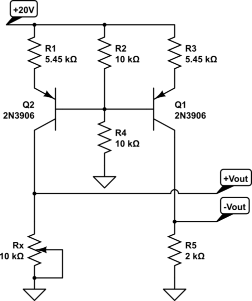
A functional circuit utilizing an operational amplifier (op-amp); however, the instructor indicated that op-amps can be challenging to work with and provided transistors as an alternative. Operational amplifiers (op-amps) are versatile components commonly used in various electronic circuits for...
R2 sets the output voltage. The maximum current is determined by the value of R3: the over-current protection circuitry inside the LM723 senses the voltage across R3 and starts shutting the output stage off as soon as this voltage...
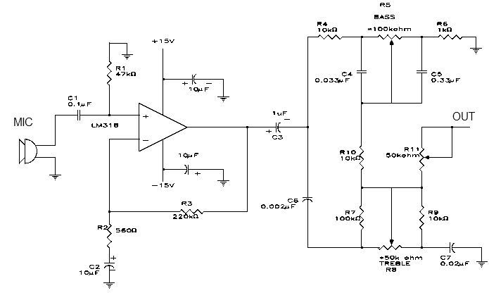
This simple microphone preamplifier is based on the LM318 operational amplifier. The LM318 operates as a standard non-inverting amplifier. Resistor R1 provides a ground input path for the bias current of the non-inverting input. The combination of R2 and...
This circuit can be used to operate an electric strike or an electromagnetic lock on a door. It is not the door being opened/closed, but a small electromagnetic strike which unlocks the door. The opener has the following features...
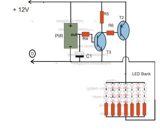
The circuit is an LED driver that responds to ambient light as well as the presence of an intruder, varying its illumination accordingly. Additionally, it includes an ambient light sensor to turn the LEDs on and off, and a...
This house FM transmitter for your stereo or any other amplifier provides good signal strength up to a distance of 500 meters with a power output of approximately 200 mW. It operates on a 9V battery. The audio-frequency modulation...
Warning: include(partials/cookie-banner.php): Failed to open stream: Permission denied in /var/www/html/nextgr/view-circuit.php on line 713
Warning: include(): Failed opening 'partials/cookie-banner.php' for inclusion (include_path='.:/usr/share/php') in /var/www/html/nextgr/view-circuit.php on line 713