
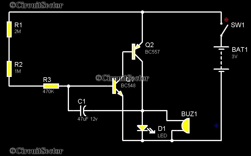
Door lock Circuit
The described circuit is designed for controlling an electric strike or electromagnetic lock, providing enhanced security and convenience for door access. The primary function of the circuit is to activate the locking mechanism, allowing for the door to be unlocked upon receiving specific input signals.
The circuit includes three main operating modes:
1. **Automatic Operation**: This mode is triggered when a guest presses the doorbell. The circuit is designed to respond immediately by energizing the electromagnetic strike, thereby unlocking the door. The automatic feature can be enabled or disabled using a switch (SW), allowing for flexibility in operation based on user preference or security needs.
2. **Manual Remote Operation**: In this mode, the unlocking mechanism can be activated by pressing a designated button (BUTTON). This allows users to unlock the door remotely, providing convenience for users who may not be directly at the door. The BUTTON is connected to the control circuitry, which processes the input signal and activates the strike.
3. **Timer Delayed Operation**: This feature allows for a timed delay before the strike is activated. The delay can be programmed to suit various operational requirements, such as allowing time for the user to approach the door after the button is pressed or the doorbell is activated. The timing function can be implemented using a timer IC, which controls the duration that the strike remains energized.
The circuit may include additional components such as diodes for flyback protection, resistors to limit current, and capacitors for noise filtering. The power supply for the circuit should be selected based on the specifications of the electric strike or lock being used, ensuring that it can deliver sufficient voltage and current for reliable operation.
Overall, this circuit design provides a versatile solution for controlling door access through an electric strike or electromagnetic lock, incorporating both automated and manual operation modes for user convenience and enhanced security.This circuit can be used to operate an electric strike or an electromagnetic lock on a door. It is not the door being opened/closed, but a small electromagnetic strike which unlocks the door. The opener has the following features currently programmed in software: * automatic operation when a guest pushes the doorbell, the strike is operated immediately - can be set by a switch (SW) * manual remote operation - by pushing a button (BUTTON), the strike is operated immediately * timer delayed operation by p 🔗 External reference
Related Circuits
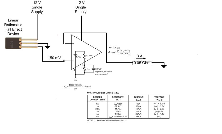
The proposed approach would dissipate (12V)(3A) = 36 watts, which results in significant heat generation in the circuit. This necessitates consideration of two alternatives: 1) Operating the op-amp at a lower supply voltage, if feasible, or 2) Utilizing a...
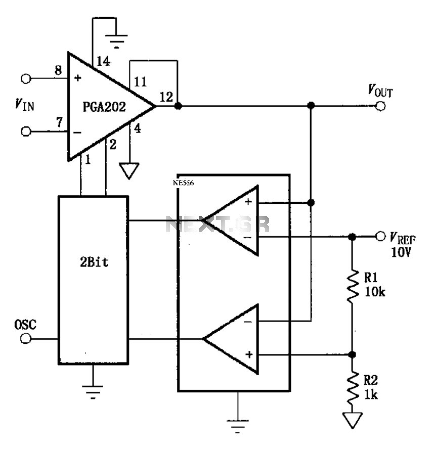
The automatic range switching circuit consists of PGA202, comparators, and counters, as illustrated in the figure. The comparator at the output compares VOUT with VREF. When VOUT exceeds 10V, the comparator generates a low signal, causing the up/down counter...
Telephones are declining globally; however, India has over 350 million mobile phone users, alongside a significant number of traditional telephone users. This telephone timer is designed to save costs by controlling unnecessary time spent during phone calls. This simple...
The voltage regulator is an LM317T, and should accept up to about 14 volts without problems. It can handle up to 1 amp, but you WILL need a heatsink on the voltage regulator. I also added DC power jacks...
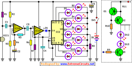
The basic circuit illuminates up to ten LEDs in sequence, following the rhythm of music or speech picked up by a small microphone. The expanded version can drive up to ten strips, each formed by up to five LEDs,...
The water tank overflow liquid level sensor alarm circuit is a straightforward electronics project suitable for school students. Previous discussions have covered numeric water level indicators and water level controller circuits, which are more complex and intended for engineering...