
LM318 microphone preamplifier circuit design
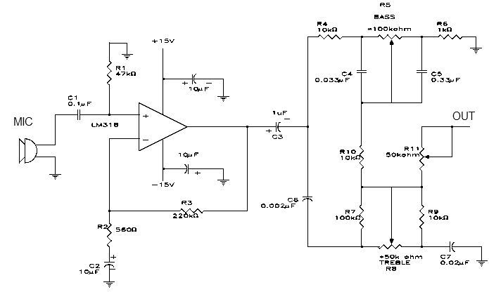
The microphone preamplifier circuit features the LM318 operational amplifier configured in a non-inverting arrangement, which is ideal for amplifying low-level audio signals from microphones. The inclusion of resistor R1 is critical as it establishes a DC path to ground for the bias current, ensuring stable operation of the non-inverting input.
The frequency response of the circuit is shaped by the components R2 and C2, which form a high-pass filter that effectively attenuates frequencies below 30 Hz. This design choice helps eliminate unwanted low-frequency noise, providing a cleaner audio signal. The gain of the amplifier is set to approximately 50 dB, achieved through the resistor ratio of R3 to R2. This gain ensures that the output signal is sufficiently amplified for further processing or mixing.
R3 plays a vital role in maintaining stability and linearity within the amplifier by providing negative feedback from the output back to the inverting input. This feedback mechanism is essential for minimizing distortion and enhancing the fidelity of the audio signal.
Capacitor C3 serves as an AC coupling component, allowing the amplified audio signal to pass while blocking any DC offset that could interfere with subsequent audio processing stages, such as tone control. The tone control section is bifurcated into bass and treble controls, with the upper half dedicated to adjusting low-frequency response and the lower half focusing on high frequencies. The use of audio taper potentiometers (R5 and R8) allows for more intuitive control over the tonal characteristics of the audio signal, providing smoother adjustments at lower levels of rotation.
Finally, the output section incorporates a 50 k ohm potentiometer, which allows for fine-tuning of the overall output level or gain of the preamplifier. This feature is particularly useful in live sound applications or recording environments where precise control over signal levels is necessary to prevent distortion or clipping in subsequent audio stages. Overall, this microphone preamplifier circuit is designed to deliver high-quality audio amplification with customizable tonal shaping capabilities.This simple microphone preamplifier is based on the LM318 op amp. The LM318 op amp is operated as a standard non-inverting amplifier. Resistor R1 provides an input path to ground for the bias current of the non-inverting input. The combination of R2 and C2 provides a frequency roll-off below 30 Hz. At 30 Hz and above the gain is relatively flat a t about 50 dB, set by the ratio R3/R2. R3 furnishes negative feedback from the output to the inverting input of the op amp. C3 ac couples the preamp to the tone control section. The top half of the tone control section is the bass control. The bottom half controls the treble frequency response. These tone controls (R5 and R8) require audio taper (logarithmic) potentiometers. The 50 k ohm potentiometer on the output can be used to set the output or gain of the preamp. 🔗 External reference
Related Circuits
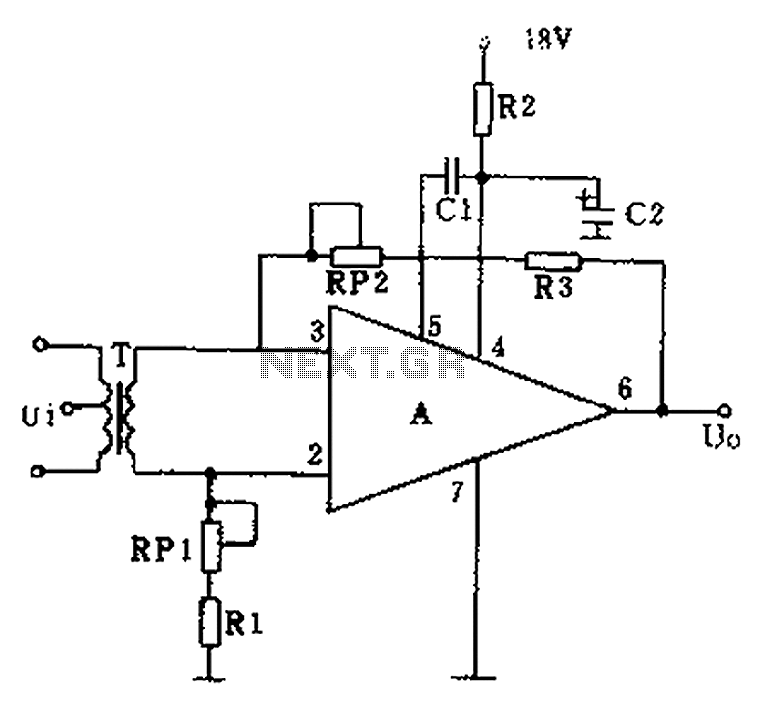
The operational amplifier A is utilized in an audio preamplifier circuit. Its advantages include compact size, low noise, low power consumption, and excellent consistency. The operational amplifier can achieve significant negative feedback while increasing output without distortion. The signal...

A simple instrumentation amplifier circuit diagram utilizing an operational amplifier (op-amp). The equation for gain, along with design, working principles, and construction details, are also provided. An instrumentation amplifier is a type of differential amplifier that has been designed to...
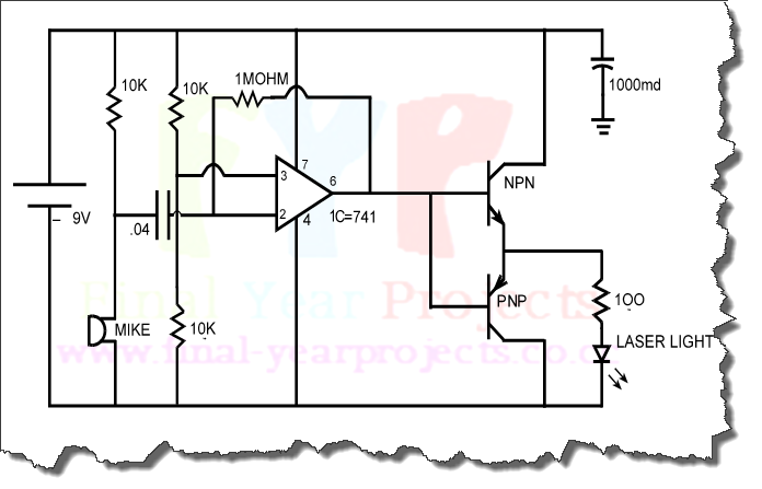
The objective of this project is to design a circuit for an electronic infrared communication system, develop innovative ideas for implementing this circuit, and study the circuitry along with various components such as DTMF generators, DTMF decoders, operational amplifiers,...
This circuit is a wireless car alarm system constructed using two modules: a transmitter module and a receiver module. It operates on FM radio waves and is suitable for vehicles with a power supply of 6-12VDC. A voltage stabilizer...
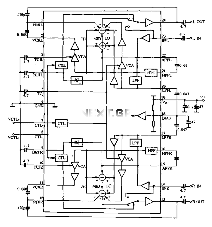
The BA3884 operates with a DC voltage range of 5.4 to 12.3V. Its internal circuit design and application circuit are represented in Figure 5-16. This circuit consists of a dual-channel processing system, which processes audio signals through two identical...
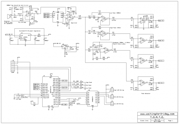
Most existing designs utilize direct switching of lights without any software control and include manual potentiometers for light sensitivity and overall gain settings. There are limited references regarding the frequency filter circuitry, explaining the specific frequencies the circuit is...