
Eggs hatching incubator circuit diagram 4

The egg hatching incubator circuit is designed to maintain optimal conditions for hatching eggs through precise temperature regulation and effective monitoring. The power supply circuit serves as the backbone of the system, ensuring that all components receive the necessary voltage and current. The inclusion of a power switch (S1) allows for convenient operation, while the fuse (FU2) protects the circuit from overcurrent situations. The power transformer (T) steps down the voltage to a suitable level, and the rectifier diodes (VD3-VD6) convert the alternating current (AC) from the transformer into direct current (DC), which is essential for the operation of the subsequent circuits.
The constant temperature control circuit is critical for maintaining the ideal environment for egg incubation. This circuit typically utilizes an electric contact thermometer, which monitors the internal temperature of the incubator. When the temperature deviates from the set point, the control mechanism activates heating elements or cooling fans to restore the desired temperature. This feedback loop ensures that the eggs are incubated under stable conditions, which is vital for successful hatching.
Additionally, the sound and light alarm circuit is an essential feature that enhances the functionality of the incubator. This circuit is designed to provide audible and visual alerts in the event of temperature fluctuations or system malfunctions. By integrating a buzzer and LED indicators, the system can effectively notify users of any critical issues that may arise, allowing for timely intervention.
Overall, the egg hatching incubator circuit is a sophisticated assembly of various electronic components working in conjunction to create a reliable and efficient environment for egg incubation. The careful design and integration of the power supply, temperature control, and alarm systems contribute to the overall effectiveness of the incubator, ensuring high hatch rates and successful outcomes.The eggs hatch incubator circuit is composed of the power supply circuit, constant temperature control circuit and sound and light alarm circuit, and it is shown in Figure 4-7. Power supply circuit consists of the power switch Sl, fuse FU2, power transformer T and rectifier diodes VD3-VD6.
Temperature control circuit consists of the electric contact thermome.. 🔗 External reference
Related Circuits
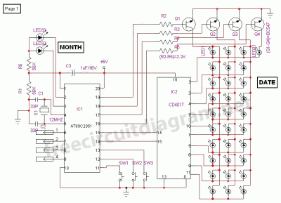
This is a digital calendar circuit that utilizes a microcontroller to display the date, day, and month on an LED display. The entire system is managed by an 8-bit microcontroller, which operates based on a program embedded in its...

An electric power limiter circuit restricts the user load, ensuring that household appliances operate within a specified normal current range. When the load exceeds a predetermined threshold, the power supply is disconnected. This circuit utilizes the high-power integrated TWH8778...
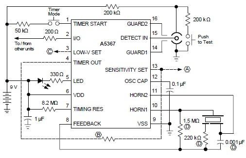
A simple ionization smoke detector with interconnect and timer alarm circuit can be constructed using the A5367 low-current, CMOS circuit, which provides all essential features for an ionization-type smoke detector. This CMOS IC, manufactured by Allegro MicroSystems, includes interconnect...
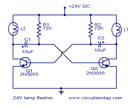
The circuit operates on 24V DC and is designed to alternately flash two 24V bulbs. It functions as an astable multivibrator with a frequency of 1Hz and a duty cycle of 50%. The lamps to be flashed are connected...
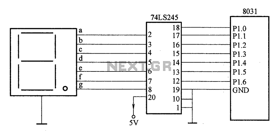
After the SCM execution, the Pl output port connects to the bidirectional input of 74LS245 driver chips. This driver operates during each phase of digital control, based on the information from the Pl port. The purpose is to convert...

This design circuit outlines a simple, low-cost, and ultra-compact VHF/UHF Low-Noise Amplifier (LNA) that can be implemented using the MAX2664 and MAX2665 devices, which are specifically tailored for VHF/UHF applications. The MAX2664 operates within the UHF frequency range of...