
88-108Mhz FM Radio Transmitter
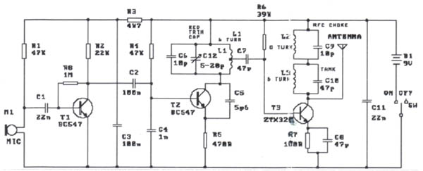
The circuit modification involves substituting two specific transistors, enhancing the performance characteristics of the circuit while maintaining its original functionality. The 2N2219 NPN transistor is well-suited for low to medium power applications, providing reliable switching capabilities, while the 2N3553 NPN transistor is designed for higher power applications, making it ideal for VHF operations. The requirement for a heatsink on the 2N3553 is critical due to its higher power dissipation, which helps to prevent overheating and ensures stable operation.
The concept of wavelength is essential in antenna design, as it directly influences the antenna's dimensions and performance. The wavelength, defined as the distance between successive peaks of a wave, can be adjusted to optimize antenna size for specific frequency ranges. By scaling the antenna down to a fraction of the wavelength, such as using harmonics, the antenna can still effectively transmit and receive signals at the desired frequency.
In the case of a dipole antenna, which consists of two conductive elements oriented in opposite directions, the length of each element should be precisely calculated to achieve resonance. By cutting the wavelength in half, each segment of the dipole antenna is configured to 75 cm, allowing for efficient radiation of electromagnetic waves. This configuration enhances the antenna's ability to operate effectively at the desired frequency while ensuring that the two elements remain out of phase, which is crucial for dipole functionality.
Proper implementation of this modification requires careful attention to the transistor specifications, thermal management, and antenna design principles to ensure optimal performance in VHF applications.The mod I present here is to use a 2n2219 NPN transistor in place of T2 and a 2n3553 NPN transistor in place of T3. Both are VHF transistors. The last transistor will need to be put on a heatsink. I haven`t found the need to make any other modifications to the circuit to make this work. Wave Length is the physical height of the wave in meters. By diving it to an acceptable length, you are making a smaller antenna resonate at the same frequency, eg one of the multiple harmonics of the wave length. If you want a dipole (180 degree out of phase antenna), cut this length in 2, so you have 75cm on the antenna output and 75cm on the positive rail and point them in oppose directions.
🔗 External reference
Related Circuits
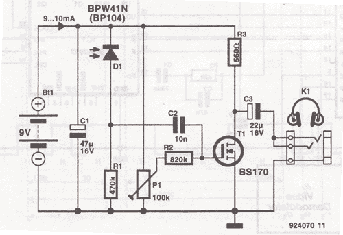
The transmitter for the wireless headphones is built around a CD4046 CMOS phase-locked loop, coupled with a driver transistor, and a pair of infrared LEDs. More: Although the CD4046 is comprised of two phase comparators, a voltage-controlled oscillator (or...
The three best known of these signals are the DCF77 signal broadcast from Mainflingen near Frankfurt in Germany on 77.5kHz which can be received throughout most of central and northern Europe. The MSF signal broadcast from outside Rugby in...

The schematic for this project is deceptively simple compared to the complexity of the circuit's operation. The two signals generated are mixed together at the base of transistor T2, and once it exits the collector of the transistor, the...
This low-cost short-wave transmitter is tunable from 10 to 15 MHz using a ½J gang condenser (VC1), which determines the carrier frequency in conjunction with inductor L1. Frequency trimming is achieved with VC2. The carrier signal is amplified by...
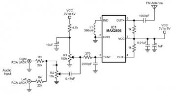
The FM transmitter circuit is built using a single MAX2606 chip. This simple FM transmitter connects a home entertainment system to a portable radio, allowing music to be played in one room and listened to in another, such as...
This wireless headphones transmitter ensures quality reception over a distance of 2 meters. The oscillator frequency ranges from 1750 kHz to 3500 kHz, and for the antenna, it... The wireless headphones transmitter operates within a frequency range of 1750 kHz...