
88-108mhz FM transmitter circuit production PCB
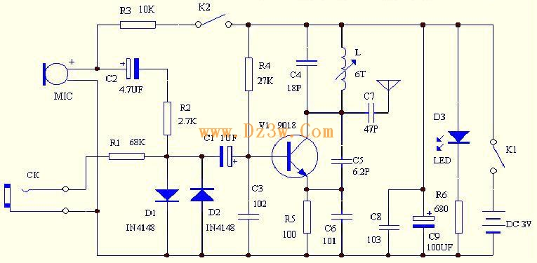
The circuit operates effectively within the FM frequency band, utilizing a resonant LC circuit formed by the capacitor C4 and inductor L. The resonator is tuned to the desired frequency range, allowing for efficient transmission of audio signals captured by the microphone. The adjustment of inductor L is critical for tuning the circuit to specific FM frequencies, which are essential for compatibility with standard FM radio receivers.
The role of R3 is vital in controlling the sensitivity of the microphone. By varying its resistance, the circuit designer can optimize the microphone's performance based on the expected sound levels in the environment, ensuring clarity in audio transmission.
The inclusion of diodes D1 and D2 as a limiter is a protective measure. By clamping the signal amplitude, the diodes prevent excessive voltage that could lead to distortion or damage to subsequent components, particularly the transistor used for modulation. This design feature enhances the robustness of the circuit, ensuring reliable operation even under varying input conditions.
The output socket CK provides versatility in connecting external audio sources, facilitating the integration of the FM transmitter with various audio devices. The attenuation network formed by R1 and the diodes ensures that the signal is conditioned appropriately before modulation, further enhancing the quality of the transmitted audio.
The operational indicator provided by LED D3 is a practical feature, allowing users to visually confirm that the microphone is active. The current-limiting resistor R6 protects the LED from excessive current, prolonging its lifespan.
Capacitors C8 and C9 play a crucial role in stabilizing the power supply, filtering out high-frequency noise that could interfere with the circuit's performance. The design consideration of using shunt capacitor C8 to minimize power supply resistance is indicative of a thoughtful approach to circuit robustness.
Lastly, the configuration of switches K1 and K2 provides operational flexibility, allowing users to select between different modes of operation while managing power consumption effectively. This aspect is particularly important in battery-operated devices, where longevity is a critical factor. The careful design of the transistor's base and emitter capacitance for frequency modulation reflects a sophisticated understanding of the principles of analog signal processing, ensuring that the circuit can accurately reproduce audio signals with minimal distortion.C4, L form a resonator: resonant frequency is the FM transmitting power of the microphone, according to the parameters of the diagram component transmission frequency can be between 88 ~ 108MHZ, just FM radio receiver covering the frequency by adjusting the value of L (La stretch or compress the coil L) can easily change the firing frequency, t o avoid the FM radio. C4 coupled to transmit signals through the antenna to launch out. 6) The resistance of R3 for the MIC to provide a DC bias, R3 of the resistance the greater the sensitivity of the sound collecting microphone weaker, the higher the resistance the smaller the sensitivity of the microphone. 8) circuits in the two diodes D1 and D2 reverse parallel, mainly from a two-way limiter functions, the diode turn-on voltage is only 0.
7V, if the signal voltage exceeds 0. 7V diode conduction will be streaming, so you can ensure that the voices of the signal amplitude can be limited to between plus or minus 0. 7V, the signal will sound too strong too modulation transistor, resulting in sound distortion can not even work properly.
9) CK is an external signal output socket, you can carry-TV headphone jack or headphone jack to listen to such external audio signal source through a dedicated connection line of the introduction of FM transmitter, external sound signal attenuation through R1 and D1, D2, after clipping sent to transistor base to frequency modulation. 10) circuit in the light-emitting diode D3 to indicate the working state, when the FM microphone was electrical work and would light up, R6 is a light-emitting diode current-limiting resistor.
C8, C9 is the power supply filter capacitor, because the big capacitor winding fabrication commonly used, so the relatively large equivalent inductance, shunt capacitor C8 can make a small high-frequency power supply resistance. 11) circuit K1 and K2 is a switch, it has three different locations, disconnect the power when appropriated for the far left, far right is the K1, K2 FM microphone connected to make use of the middle position is K1 connected, K2 off do the wireless transponder use, as do the wireless repeater use is the microphone does not work, but the microphone will consume certain amount of quiescent current, it can reduce the power off K2, extend battery life.
By changing the transistor base and the emitter capacitance to achieve between the FM, when the audio voltage signal added to the base on the transistor, the transistor base and the emitter capacitance between the size of the place as the voice of voltage signal synchronization changes, while the launch of the frequency change in transistor to achieve frequency modulation. 🔗 External reference
Related Circuits

The LA4440 is a dual-channel audio power amplifier integrated circuit (IC) designed for stereo and bridge amplifier applications. In dual mode, it provides significant audio amplification for various audio systems. The LA4440 audio power amplifier is engineered to deliver high-quality...
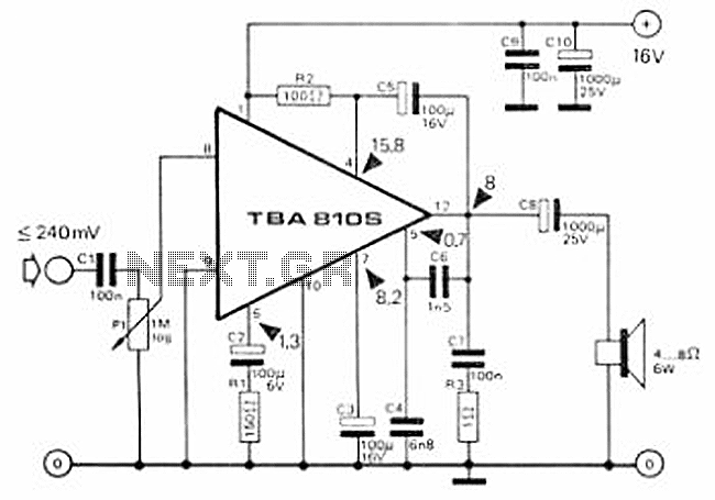
This circuit is a 7 Watt audio amplifier that is simple and easy to construct. It utilizes the TBA810 as the primary component, supported by a few passive components. The amplifier operates effectively, and the necessary kits and components...
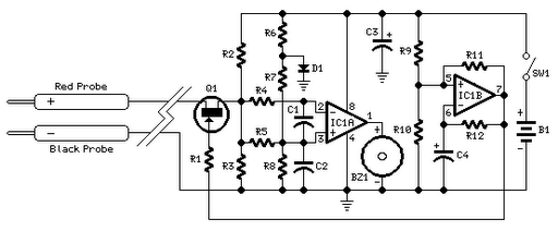
Short circuits or broken PCB tracks can be easily identified using a multimeter; however, this tool may yield inaccurate results when testing the efficiency of a transistor or diode unless the component is unsoldered and removed from the PCB....
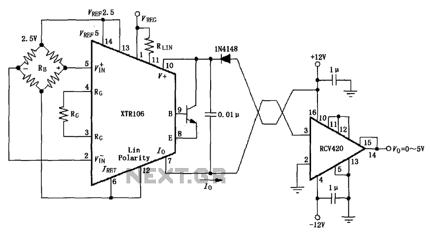
The IN4148 series diode is connected in the V+ line and configured in a loop to prevent damage from reverse voltage conditions. The diode exhibits a forward voltage drop of approximately 0.7V, which affects the supply voltage. The circuit...
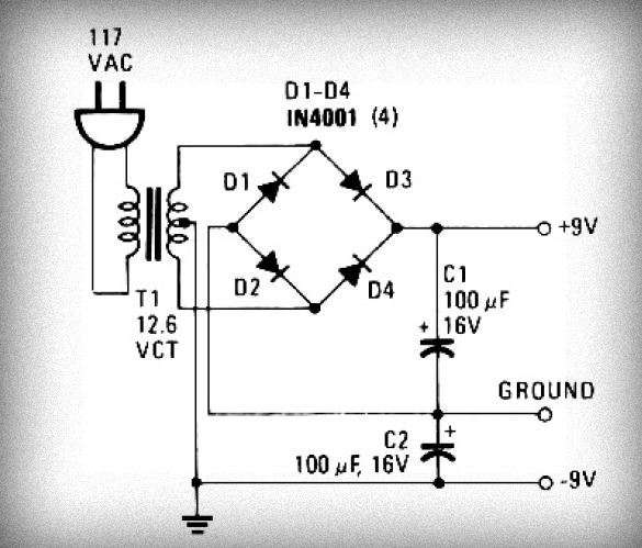
Initially, voltage from AC 220V or 110V enters the transformer, which reduces it to 12V AC. This AC voltage is then rectified using either four diodes or a bridge rectifier to convert it to DC voltage. The resulting DC...
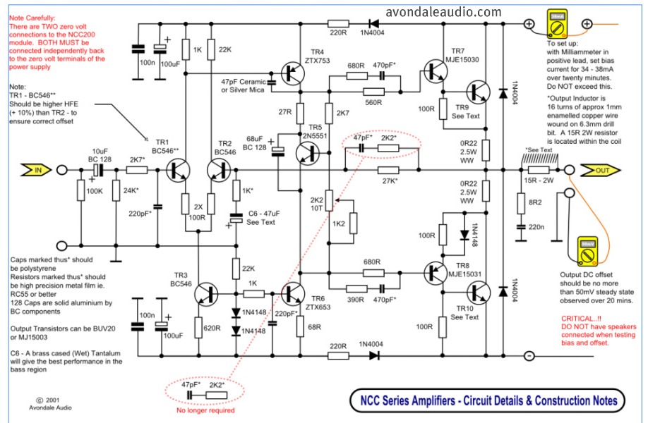
This is a simple circuit that features high-performance power amplifiers. The power amplifier is available as a PCB, along with a complete list of components. The described circuit utilizes high-performance power amplifiers, which are essential for applications requiring significant signal...
Warning: include(partials/cookie-banner.php): Failed to open stream: Permission denied in /var/www/html/nextgr/view-circuit.php on line 713
Warning: include(): Failed opening 'partials/cookie-banner.php' for inclusion (include_path='.:/usr/share/php') in /var/www/html/nextgr/view-circuit.php on line 713