
XTR106 and send RCV420 composed of 12V power supply reception circuit diagram of the ring
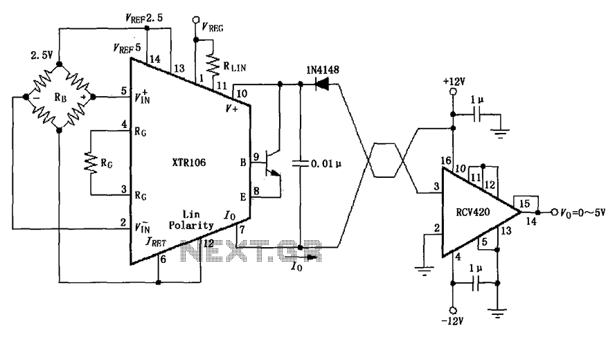
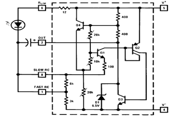
The IN4148 diode is a widely used silicon switching diode known for its fast switching speed and reliability in various electronic applications. In this circuit, the diode's primary role is to protect the circuit from potential reverse voltage that could cause damage to sensitive components. When implemented in the V+ line, the diode allows current to flow in the forward direction while blocking reverse current, thereby safeguarding the integrity of the power supply.
The forward voltage drop of 0.7V represents a minor voltage loss in the circuit, which should be accounted for in the overall power supply design. This drop can influence the voltage levels experienced by downstream components, especially in low-voltage applications where every millivolt is crucial.
The configuration also features a positive nonlinear correction bridge connection. This setup typically involves a combination of diodes arranged in a bridge configuration to rectify AC voltage into DC, providing a stable output voltage. The nonlinear correction aspect may refer to additional components or circuitry designed to enhance the performance of the rectifier, ensuring that the output maintains a consistent voltage despite variations in input conditions.
In summary, the integration of the IN4148 diode in the V+ line serves as an effective protective measure against reverse voltage while contributing to the overall functionality of the circuit through its forward voltage characteristics and its role in the bridge connection. Proper consideration of the diode's specifications and its placement within the circuit is essential for optimal performance and reliability. As shown, the diode IN4148 series in V + and loop to prevent line damage due to reverse device in the loop loss only 0.7V (silicon diode forward voltage drop) of the power supp ly voltage. FIG Lin Polarity positive nonlinear correction bridge connection.
Related Circuits
This project involved the design of an audio amplifier capable of delivering substantial output power with minimal component count while maintaining high quality. The power amplifier section utilizes three transistors along with a few resistors and capacitors in a...

Universal Power Supply Module 3V-30V power supply. Refer to the specified page for an explanation of the related circuit diagram. This power supply circuit is paired with a high-power audio amplifier rated at 1500 watts. The design of the...
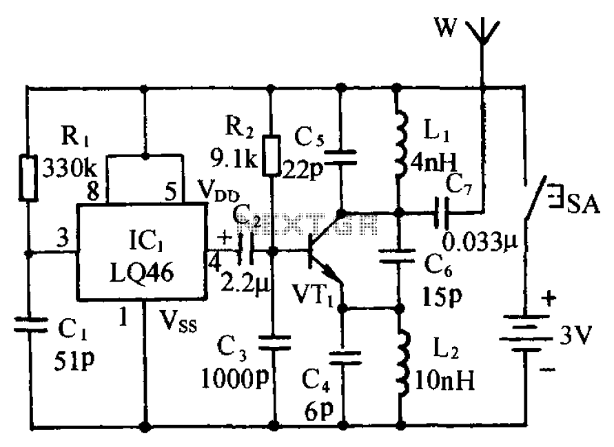
The circuit is presented, consisting of a language and sound circuit FM transmitter. It is simple and easy to manufacture, compatible with ordinary FM radios, allowing for potential listening scenarios and preventive measures. The FM transmitter circuit is designed to...
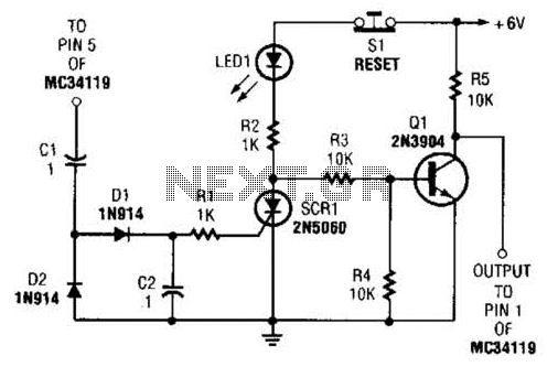
The ear protector is a peak audio detector and shutdown circuit that disables the amplifier through its chip-disable input when the output volume of the amplifier reaches a predetermined level. Although designed for the MC34119 amplifier, the circuit should...
TV video signal processor circuit. The ECG1064 chip includes a primary video amplifier, two sync pulse amplifiers, a look-out protector, a noise detector, two noise gates, an automatic gain control (AGC) detector, an intermediate frequency (IF) AGC amplifier, a...
The schematic diagram below illustrates a typical 1.5V flasher circuit using the LM3909. The LM3909 is a monolithic oscillator designed specifically for flashing Light Emitting Diodes (LEDs). The LM3909 flasher circuit operates at a low voltage of 1.5V, making it...