
8W Flouroscent lamp driver

The fluorescent lamp driver circuit is designed to operate efficiently by utilizing two transistors configured as an oscillator. The transistors, specifically the 2SC 1983 model, are chosen for their suitability in switching applications and high-frequency operation. The oscillator generates a frequency of around 1 kHz, which is ideal for driving fluorescent lamps, as it allows for effective excitation of the gas within the tube.
Capacitive ballasting is employed in this design to limit the current flowing through the fluorescent tube, preventing excessive heating and prolonging the lamp's lifespan. The circuit architecture ensures that the transistors do not enter saturation, which is critical for maintaining a stable output and reducing power losses. This design consideration results in a cleaner sine wave output, characterized by low harmonic distortion and minimal electromagnetic interference.
The transformer design is integral to the circuit's operation. The primary winding, constructed with 0.8 mm diameter enameled copper wire, should be wound first around the ferrite core. The secondary winding, made with 0.4 mm diameter enameled copper wire, is then wound on top of the primary. The number of turns for each winding is specified in the schematic, which is crucial for achieving the desired voltage transformation and ensuring that the fluorescent tube operates efficiently.
Overall, this circuit represents a practical and effective solution for driving fluorescent lamps, balancing efficiency, performance, and simplicity in its design.Here is the schematic of a simple flouroscent lamp driver circuit based on two transistors. The circuit uses capacitive ballasting for driving the tube. An 8 W standard flouroscent tube can be efficiently driven using the circuit. The two transistors (2Sc 1983) with associated components forms a oscillator around 1KHz. The oscillator is wired so that saturation condition of the transistors are prohibited. This adds on to the efficiency of the circuit. The circuit produces a clean sine wave with very less noise. The winding details(no of turns) are given in the circuit. Use 0. 8 mm dia enameled copper wire for primary and 0. 4 mm dia enameled copper wire for secondary. The core can be a ferrite core. The primary should be wound first and secondary on top of it. 🔗 External reference
Related Circuits
This 40W fluorescent lamp inverter enables the operation of 40W fluorescent tubes using any 12V source that can provide 3A. It is essentially a larger variant of the 12VDC Fluorescent Lamp Driver and can be utilized to illuminate both...
Savings on electricity bills can be achieved by utilizing alternative power sources. The photovoltaic module, or solar panel, described here can provide a power output of 5 watts. Under full sunlight conditions, the solar panel generates an output voltage...
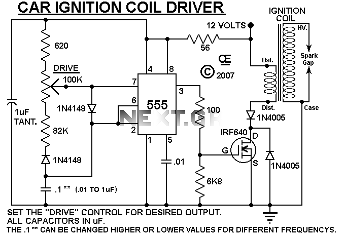
A simple design based on a 555 to drive a car ignition coil. This was designed for a small electric fence to protect a vegetable garden from small animals called marmots. Last year, they ate one of the crops...
As an alternative to a bipolar transistor, a lamp flasher can be constructed using two power FETs. Similar to other flasher circuits, this circuit alternately switches the... The proposed lamp flasher circuit utilizes two power Field-Effect Transistors (FETs) to control...
Depending on its design, an electric guitar may have anywhere from one to six pickup elements. Classic acoustic guitars can also benefit from one or more retrofitted pickups. Each pickup produces a specific sound based on the type of...
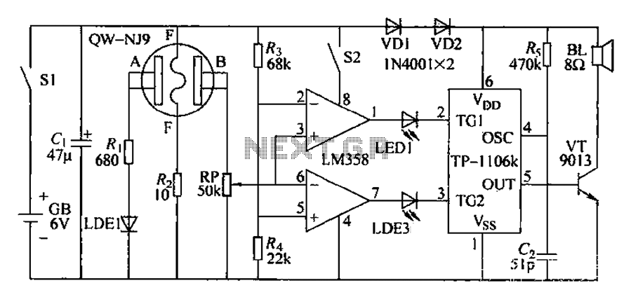
Car drivers and motorcyclists, despite prohibitions against drinking and driving, may still engage in this dangerous behavior. In such cases, the circuit can detect the presence of alcohol. If alcohol is detected, a warning message is issued immediately. If...