
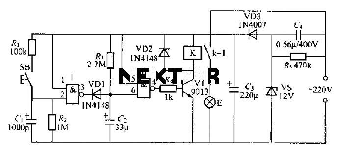
Power FET Lamp Flasher
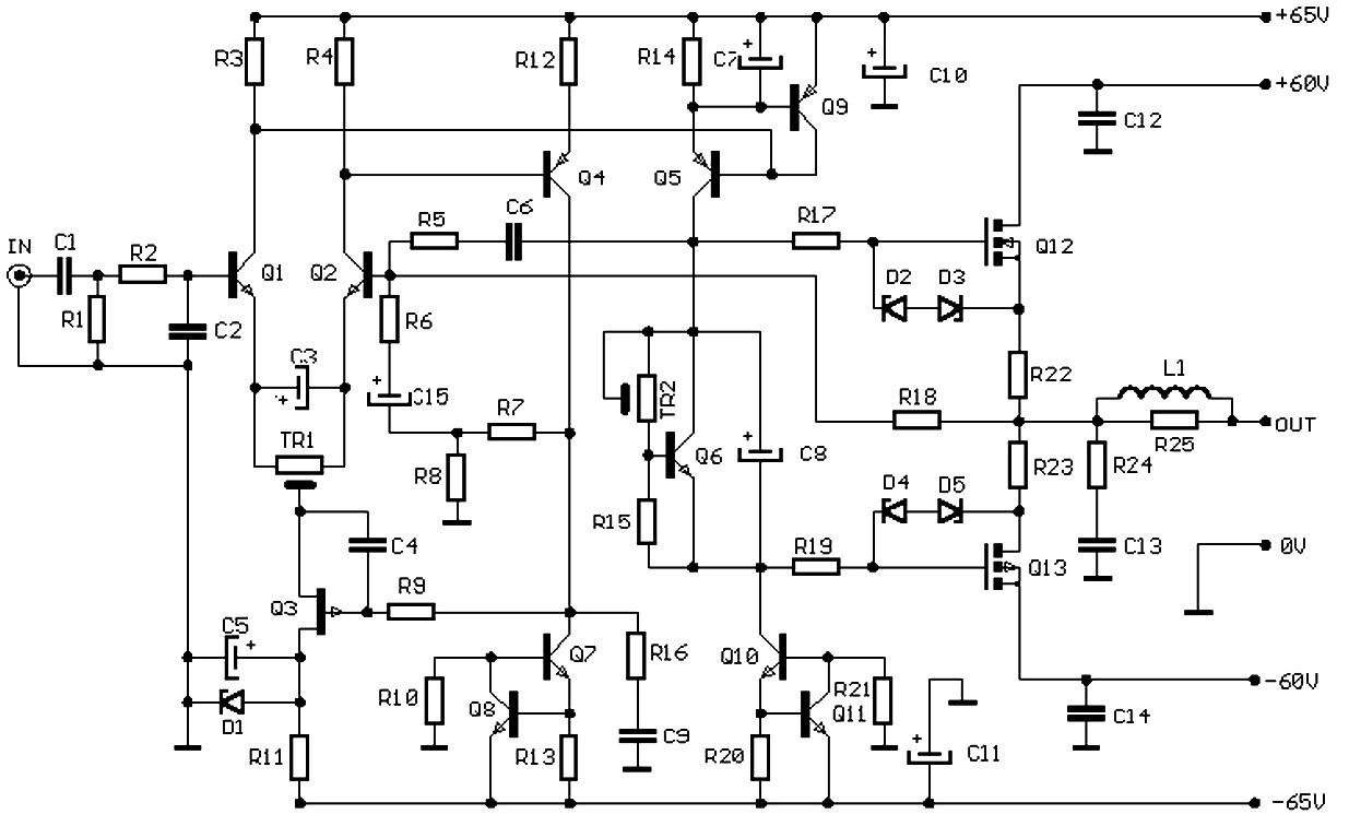
The proposed lamp flasher circuit utilizes two power Field-Effect Transistors (FETs) to control the alternation of a lamp's illumination. This design offers several advantages over traditional bipolar transistor circuits, including higher efficiency and faster switching times.
In this configuration, the two power FETs are arranged in a complementary manner, allowing one FET to conduct while the other is off, and vice versa. This creates a pulsing effect that can be adjusted for various flashing rates by incorporating a timing circuit, typically based on a resistor-capacitor (RC) network or a microcontroller.
The circuit begins with a control signal that triggers the first FET, allowing current to flow through the lamp, which illuminates. Once the control signal is removed, the first FET turns off, and the second FET is activated, completing the circuit and allowing the lamp to flash alternately. This switching can be controlled through various means, such as a timer IC, a 555 timer, or a microcontroller, which can provide precise timing adjustments.
The use of power FETs in this application enhances the thermal performance of the circuit, as they typically have lower on-resistance compared to bipolar transistors, resulting in reduced power loss and heat generation during operation. Additionally, the FETs can be driven directly by low-voltage logic signals, simplifying the control circuitry.
To ensure reliable operation, it is essential to include protection components such as diodes to prevent back EMF from inductive loads, which can damage the FETs. Proper heat sinking may also be required to dissipate heat generated during operation, particularly at higher current levels.
Overall, this lamp flasher circuit design with power FETs presents an efficient and reliable alternative to traditional bipolar transistor-based designs, suitable for various applications in lighting control systems.As an alternative to bipolar transistor, a lamp flasher can be built by using two power FETs. Like other flasher circuit, this circuit alternately switch the.. 🔗 External reference
Related Circuits
This is a driver circuit for a nixie tube. The circuit utilizes the 2N3684 transistor as the nixie tube driver due to its Vp rating of 2-5 volts, which ideally matches TTL-DTL logic levels. The nixie tube driver circuit is...

For systems with a single power supply, two operational amplifiers function as instrumentation and buffer amplifiers. The OPA111 AM buffers the reference mode of the bridge and applies that voltage to the reference terminal of the instrumentation amplifiers. The...
This system serves as the power supply for all the circuitry within the robot, as illustrated in the block diagram. Housed within an aluminum enclosure are the NiMH cells along with the previously described circuits. Two lines of preregulators...
A 2-input NAND gate integrated circuit is used in the fabrication of a digital delay lamp circuit. This circuit is energized by a simple capacitive voltage rectifier, which operates by crossing the half line. The output terminal indicates the...
This balanced preamplifier circuit is designed to amplify low-level audio signals (from 0 dB to 20 dB) and features balanced inputs and outputs. The design utilizes standard components that are readily available in the electronics market. The balanced preamplifier circuit...
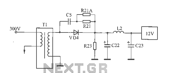
The 12V voltage instability should first be investigated by checking the output section of the switching power supply, as illustrated in the accompanying figure. The secondary winding of the transformer and the switch VD4 have been examined and found...
Warning: include(partials/cookie-banner.php): Failed to open stream: Permission denied in /var/www/html/nextgr/view-circuit.php on line 713
Warning: include(): Failed opening 'partials/cookie-banner.php' for inclusion (include_path='.:/usr/share/php') in /var/www/html/nextgr/view-circuit.php on line 713