
8x8x8 LED Cube

A comprehensive electronic schematic for the described LED lattice and controller system includes multiple elements. The power supply section should be designed to deliver a stable 3V output, accommodating the operational requirements of the LEDs. The LED array is organized in an 8x8x8 configuration, with each LED connected in a series-parallel arrangement to ensure uniform brightness and stability.
The controller schematic will incorporate microcontroller sockets that facilitate the programming and control of the LED array. Ensure that the microcontroller has sufficient GPIO pins to manage each row and column of LEDs independently. The common GND and VCC lines should be clearly indicated, with appropriate decoupling capacitors placed near the power pins of the microcontroller to minimize voltage fluctuations.
In addition, the layout should include traces for the additional wires that connect each row of LEDs to the controller, allowing for dynamic control over individual LEDs. The use of resistors in series with the LEDs is crucial to limit the current and prevent damage. Each LED's cathode should connect to the designated row wire, while the anodes connect to the corresponding column traces on the PCB.
The schematic should also illustrate the placement of the status LED and any optional components, such as a power switch. Proper grounding and power distribution must be maintained throughout the design to ensure reliability and performance. The final assembly should be tested thoroughly to confirm that all connections are functional and that the LEDs operate as intended.You will need 512 properly working LEDs in the lattice. They will need to be stable and bright. This step will show you how to separate the faulty ones from the usable ones. Lots of times there are broken LEDs, especially when they come in large packages. The damage may be noticeable but sometimes it is not. Start by bending the shorter leg (the cathode) at a 90 degree angle. Hook it up to a power supply and run 3V across it. You can do this with 2 AA batteries in series, but I had a power supply with alligator clips. Either way, just make sure the LEDs are working before you begin to solder. Create an 8x8x8 template so you can create the layers. You will need a peg board and you will need to drill holes into the peg board to space the LEDs 1/2" apart. I put foil over my rig to hold the LEDs in place so that they wouldn`t move while I solder, otherwise theywould jiggle to much.
Use the LEDs to punch holes into the foil. The picture should show you how to do it, but basically have all of the LEDs in the row facing the same way. Begin with the corner first. The corner row should be 90 degrees facing the other way. You should also align each LED so it is just barely touching the next one. When you solder, don`t hold the iron more than 2 seconds on the LED, otherwise it can be damaged. Apply minimal solder between each LED. Cut a piece of wire longer than the length of your layer and strip off the insulation. Place the long, stripped wire into a vice and pull hard to straighten it. You can do this with another set of pliers as well. You should feel the wire get longer and straighter as you pull. Once it is straight enough, place it on the opposite end of the layer and solder it on the cathodes to stabilize the rear end.
Do this once more for the middle section, as now it is the weakest part of the layer. I used clips to hold the reinforcement bar in place while I soldered. These bars should strengthen the rear and middle of the cube so it won`t break. I used triangular folds of paper to hold each layer above the other when I soldered. Make sure to place the first layer in the rig and start from there. I would recommend bending the leads slightly so you can have each layer directly above the other, otherwise it can come out slightly crooked. Apply minimal heat and solder, and be careful when going into the cube with the iron. Read Step 10 before you begin to solder. The final step in lattice construction. These eight extra wires will drop down from each row to connect them to the board. So far, we have column connections but with these lines we will be able to control individual LEDs by separating the columns and rows apart.
Do this by stripping wire as before and creating hooks at the end to secure each to its layer. Use solder to hold in place only at the row each line is designated for. Make sure each line only touches its layer and no other. They should extend the same length as the bottom-most legs. It should look something like this, although mine came out slightly rectangular because I spaced the layers out more than half an inch. Ultimately, this won`t affect animations but it adds a personal effect to it. Now let`s start on the controller. Start by placing the chip sockets next to each other but leave enough room for resistors and headers.
I would advise to economize space but to leave yourself enough room to solder and place wires. Allocate a common GND and VCC line that will connect to each socket. I used small 0. 1uF capacitors that are placed in betweeneach socket for the VCC and GND line. The black wires are for the common GND line. VCC goes to pin 20 and GND goes to pin 10. Refer to the schematic in Step 12 for the rest of the steps. This is the power portion of the controller board. It consists of a couple of capacitors and a status LED. Follow the top most diagrams in the schematic. You may or you may not want to include a power switch. I didn`t. Conne 🔗 External reference
Related Circuits
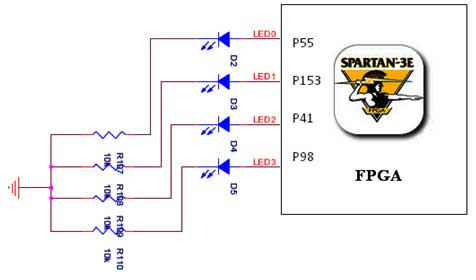
The Spartan-3E board features four LEDs connected to FPGA I/O pins, as detailed in the accompanying table. Each LED's cathode is connected to ground through a 330-ohm resistor. To illuminate a specific LED, the corresponding FPGA control signal must...
To make an LED function, a voltage source is required that exceeds the LED's forward bias voltage, which is typically greater than 1.5V (approximately 2V for red LEDs). To effectively operate an LED, it is essential to provide a voltage...
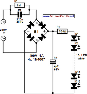
An array of white LEDs can serve as a small lamp for the living room. LED lamps are readily available, resembling standard halogen lamps, and can be installed in a standard 230-V light fixture. A capacitor is employed to...
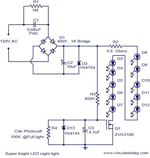
The circuit diagram illustrates a super bright LED night lamp that operates from the mains supply. A bridge rectifier (D1) is employed to convert the AC mains voltage into DC. The combination of capacitor (C1) and resistor (R1) forms...
The clock circuit above uses seven ICs and 19 LEDs to indicate binary coded decimal time. The LEDs can be arranged so that each horizontal group of 3 or 4 LEDs represents a decimal digit between 0 and 9...
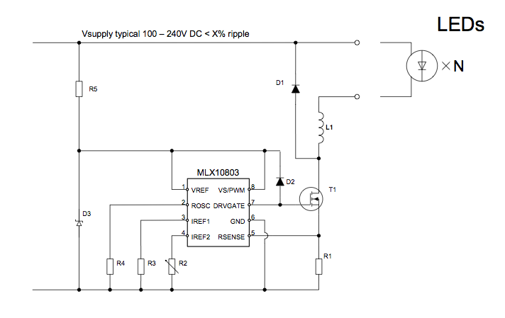
The applications outlined in this document pertain to driving high-power LED diodes. The circuits described can also be utilized in other applications with similar requirements, as long as they adhere to the specifications of the MLX10803. This is a...