
Mains Powered White LED and Grand Prix Starting Lights circuit
This circuit emulates the starting light sequence currently utilized by FISA for Formula One racing and can be adapted for slot car sets (such as HO scale AFX/Life Like/Tyco sets) or radio-controlled cars. The 555 timer IC (IC1) operates as a clock pulse generator, with its output directed through NAND gates (IC2a and IC2c) to a 4024 binary counter (IC3). IC2b inverts the O4 output of the 4024 binary counter. Initially, IC3 is reset, resulting in all outputs being low, including O4. This condition presents a logical high to the pin 8 input of IC2c, allowing clock pulses from the 555 timer to be passed to the clock input of the 4024. As IC3 counts, upon reaching binary 1111, the subsequent pulse sends the O4 output of IC3 high, disabling IC2c and halting the counting process.
The four utilized outputs of IC3 connect to a resistor ladder that functions as a simple digital-to-analog converter (DAC). As the count increases, the voltage at the top of the ladder also increases, which connects to the inverting inputs of four comparators within IC4 (an LM339) and to IC5, a 741 op-amp configured as a comparator. The positive inputs of the comparators are linked to a voltage divider, with the tapping voltages adjustable via VR1, a 100 kΩ trimpot. As IC3 counts, the ascending stepped voltage from the DAC ladder sequentially activates the comparators, starting with IC4d and progressing to IC5. Each activated comparator lights its corresponding pair of LEDs, beginning with LEDs 1 & 2, followed by LEDs 3 & 4, and continuing in this manner. When all five pairs of LEDs are illuminated, the next pulse from IC1 increments the binary count of IC3 to 10000, causing the DAC voltage to drop to zero and extinguishing all LEDs. Simultaneously, counting ceases, as the high signal on O4 prevents further gate pulses to IC2c. The circuit remains inactive until the counter is reset by pressing pushbutton switch S1, allowing a new sequence to commence.Did it ever occur to you that an array of white LEDs can be used as a small lamp for the living room If not, read on. LED lamps are available ready-made, look exactly the same as standard halogen lamps and can be fitted in a standard 230-V light fitting.
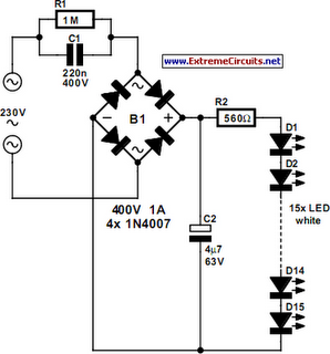
We opened one, and as expected, a capacitor has been used to drop the voltage from 230 V to t he voltage suitable for the LEDs. This method is cheaper and smaller compared to using a transformer. The lamp uses only 1 watt and therefore also gives off less light than, say, a 20 W halogen lamp. The light is also somewhat bluer. The circuit operates in the following manner: C1 behaves as a voltage dropping resistor` and ensures that the current is not too high (about 12 mA). The bridge rectifier turns the AC voltage into a DC voltage. LEDs can only operate from a DC voltage. They will even fail when the negative voltage is greater then 5 V. The electrolytic capacitor has a double function: it ensures that there is sufficient voltage to light the LEDs when the mains voltage is less than the forward voltage of the LEDs and it takes care of the inrush current peak that occurs when the mains is switched on.
This current pulse could otherwise damage the LEDs. Then there is the 560-ohm resistor, it ensures that the current through the LED is more constant and therefore the light output is more uniform. . This circuit reproduces the starting light sequence currently used by FISA for Formula One racing. It could be used with slot car sets (such as HO scale AFX/Life Like/Tyco sets) or radio controlled cars.
IC1, a 555 timer IC, is used as a clock pulse generator. Its output is fed via NAND gates IC2a and IC2c to IC3, a 4024 binary counter. IC2b inverts the O4 output of 4024 binary counter IC3. Initially, IC3 is reset and all its outputs are low, including O4, which causes IC2b to present a logical high to the pin 8 input of IC2c which then passes pulses from the 555 clock circuit to the clock input of the 4024. IC3 then begins counting. After the count has reached binary 1111, the next pulse sends the O4 output of IC3 high, which disables IC2c and IC3 stops counting.
The four used outputs of IC3 are connected to a resistor ladder` which acts as a simple digital to analog convert-er (DAC). As the count increases so does the voltage produced at the top of the ladder and this is connected to the inverting inputs of four comparators inside IC4 (an LM339) and to IC5, which is a 741 op amp also connected as a comparator.
The positive inputs of the comparators are connected to the taps of a voltage divider, with the tapping voltages set using VR1, a 100kO trimpot. As IC3 counts, the rising stepped voltage from the DAC ladder switches the comparators on in sequence, starting with IC4d and working up to IC5.
As each comparator is turned on, its pair of LEDs is lit; first LEDs 1 & 2, then LEDs 3 & 4 and so on. When all five pairs of LEDs are lit, the next pulse from IC1 moves the binary count of IC3 to 10000, so the DAC voltage drops back to zero and all LEDs are extinguished.
At the same time, counting also stops, because the high on O4 causes IC2c to block further gate pulses. The circuit then remains inactive until the counter is reset by pressing pushbutton switch S1. This allows a new sequence to begin. 🔗 External reference
Related Circuits
The 22-watt amplifier is straightforward to construct and cost-effective. This circuit can serve as a booster in a car audio system, an amplifier for satellite speakers in a surround sound or home theater setup, or as an amplifier for...

This circuit is designed for tone control utilizing a three-band equalizer. It is based on the LF351 single-chip operational amplifiers. The circuit features three adjustable ranges: bass, mid, and treble controls. The equalizer allows for approximately +/-20 dB of...
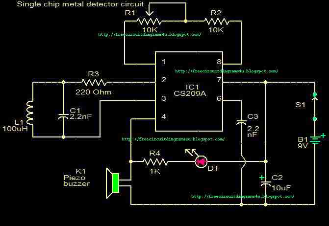
This circuit is a single chip metal detector. Actually, we can use this one to detect metals. Especially, you have seen some army soldiers keep something to detect metals. That equipment has been made through this circuit. So you...
This project uses the 1.2v rechargeable battery and solar panel from a Solar Garden Light. These lights can be bought for less than $5.00 in most $2.00 shops or similar shops that sell general household items. We are also...

This is a schematic and block diagram of a 2-MHz frequency counter. It utilizes an LSI counter/display driver, an LCD readout, and several logic chips for timebase and timing pulse circuitry. Q2 and Q3 serve as a signal (input)...
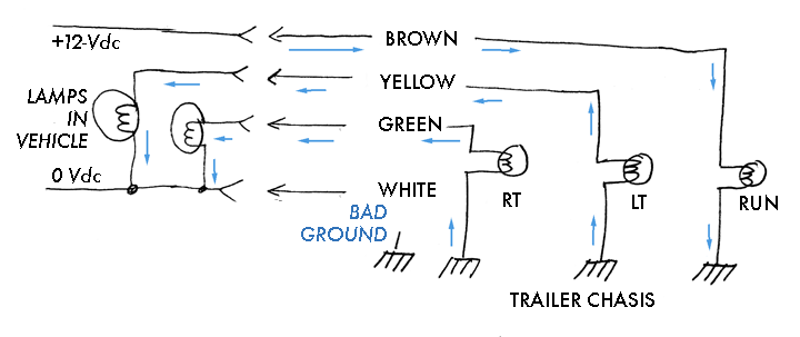
The boat trailer wiring was rewired due to damaged wiring and lights. A standard 4-pole flat connection is used to connect to the truck. The trailer features two rear lights and no side markers, with both rear lights grounded...