
9 Second Digital Readout Countdown Timer
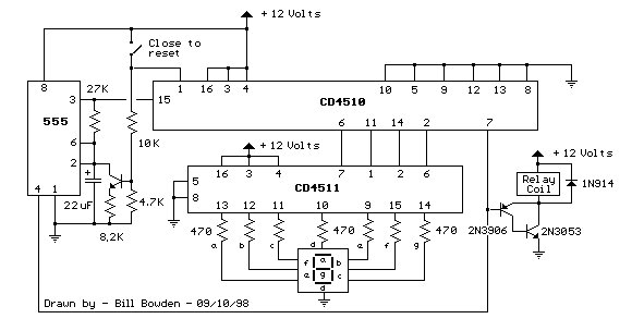
The described circuit utilizes a CD4010 IC, which is a dual 4-bit up/down binary counter. The counter is initialized to 9 when the switch is closed, allowing for a countdown sequence to begin. The 555 timer, configured in astable mode, is initially disabled to prevent any clock signal from being generated during this preset phase.
Once the switch is opened, the 555 timer is activated, generating a clock pulse approximately every second. This clock pulse is fed into the clock input of the CD4010 counter, decrementing the counter's value by 1 for each pulse. As the counter counts down from 9 to 0, the output of the counter is connected to a 7-segment display, which visually indicates the current count.
The design of this circuit ensures that the visual representation of the countdown is clear and straightforward. The 7-segment display is typically driven by the outputs of the CD4010, which are decoded to activate the appropriate segments of the display for each count.
This circuit can be effectively used in applications that require a timed visual indication, such as countdown timers or delay circuits in various electronic projects. The combination of the CD4010 and the 555 timer provides a reliable and simple method for achieving a precise timing function with visual feedback.This circuit provides a visual 9 second delay using a 7 segment digital readout LED. When the switch is closed, the CD4010 up/down counter is preset to 9 and the 555 timer is disabled with the output held high. When the switch is opened, the timer produces an approximate 1 second clock signal, decrementing the counter until the 0 count is reached.
When the.. 🔗 External reference
Related Circuits
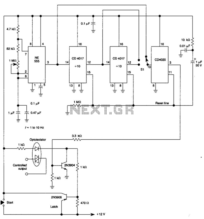
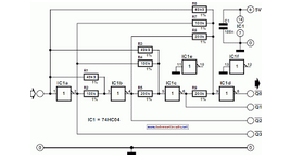
By using three 555 ICs, three sequential pulses can be generated. Output 3 can be connected back to the trigger input to achieve astable operation. The circuit described utilizes three 555 timer integrated circuits (ICs) configured to generate three sequential...
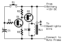
This device is a simple timer, allowing to keep on the headlights of your vehicle for about 1min. and 30sec., e.g. when accessing some dark place, without the necessity of coming back to switch-off the lights. The circuit design for...
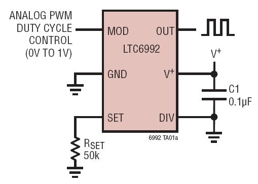
The LTC6990 is a precision silicon oscillator with a programmable frequency range of 488Hz to 2MHz. It can function as either a fixed-frequency oscillator or a voltage-controlled oscillator (VCO). The LTC6990 belongs to the TimerBlox family of versatile silicon...
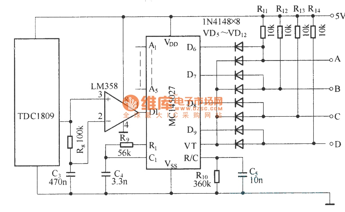
The TDC1808/TDC1809 is a pair of wireless remote control transmitter and receiver components. They utilize an internal antenna to transmit both digital and analog signals. These components are suitable for various wireless remote control devices. Key features include compact...
The operation of the converter is based on the weighted addition and transfer of the analog input levels to the digital output levels. It consists of... The converter functions by utilizing a weighted summation technique to process analog signals and...
Warning: Missing argument 2 for wpdb::prepare(), called in /home3/nithish/public_html/btechzone.com/wp-content/plugins/sharebar/sharebar.php on line 112 and defined in /home3/nithish/public_html/btechzone.com/wp-includes/wp-db.php on line 992 Warning: Missing argument 2 for wpdb::prepare(), called in /home3/nithish/public_html/btechzone.com/wp-content/plugins/sharebar/sharebar.php on line 124 and defined in /home3/nithish/public_html/btechzone.com/wp-includes/wp-db.php on line 992 This...
Warning: include(partials/cookie-banner.php): Failed to open stream: Permission denied in /var/www/html/nextgr/view-circuit.php on line 713
Warning: include(): Failed opening 'partials/cookie-banner.php' for inclusion (include_path='.:/usr/share/php') in /var/www/html/nextgr/view-circuit.php on line 713