
Three Stage Sequential Timer Circuit
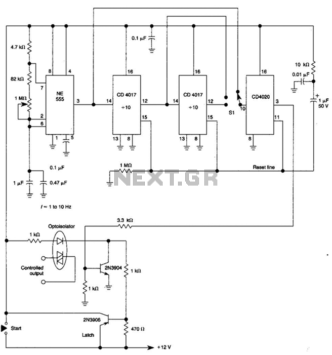
The circuit described utilizes three 555 timer integrated circuits (ICs) configured to generate three sequential output pulses. The 555 timer operates in monostable or astable modes, and in this configuration, it is likely set up in a monostable mode for each of the three timers.
In this arrangement, the output of the first 555 timer is connected to the trigger input of the second 555 timer. When the first timer is triggered, it generates a pulse that activates the second timer. Similarly, the output of the second timer is connected to the trigger input of the third timer, thereby allowing for a cascading effect where each timer sequentially activates the next.
To achieve astable operation, the third 555 timer's output can be connected back to its trigger input. This feedback loop enables continuous oscillation, producing a square wave output. The frequency and duty cycle of the output pulses can be controlled by adjusting the resistors and capacitors connected to each 555 timer.
The output from each timer can be used in various applications, such as generating clock signals for digital circuits, controlling timing sequences in automation systems, or creating sound signals in audio applications. Proper selection of component values is crucial for achieving the desired pulse width and frequency for each stage of the circuit.
Overall, this configuration of 555 timers provides a versatile solution for generating sequential pulses and can be adapted for various electronic applications. By using three 555 ICs, three sequential pulses can be generated. Output 3 can be connected back to trigger input to achieve astable operation. 🔗 External reference
Related Circuits

This circuit is designed to allow voice clarity over music playback. It is particularly useful for DJs, small radio stations, announcements over music in shops, and similar applications. Additionally, it can be utilized in scenarios where voice control is...
Low-noise preamplifier circuit. This circuit demonstrates a typical low-noise preamplifier design, which can be utilized to amplify signals from sources such as magnetic heads and microphones within audio applications. The input signal is coupled through a capacitor and subsequently...
This is a programmable clock timer circuit that uses individual LEDs to indicate hours and minutes. 12 LEDs can be arranged in a circle to represent the 12 hours of a clock face and an additional 12 LEDs can...
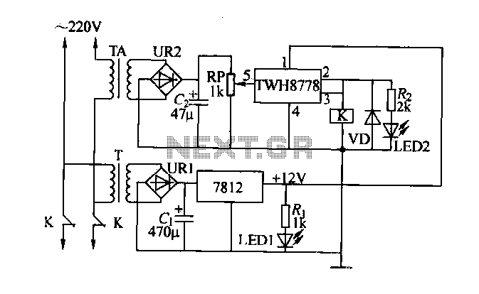
An electric power limiter circuit restricts the user load, ensuring that household appliances operate within a specified normal current range. When the load exceeds a predetermined threshold, the power supply is disconnected. This circuit utilizes the high-power integrated TWH8778...
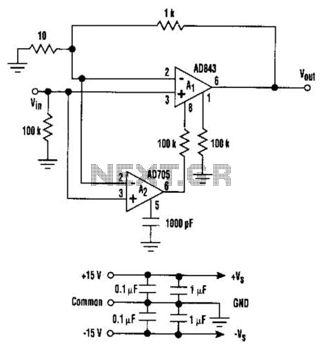
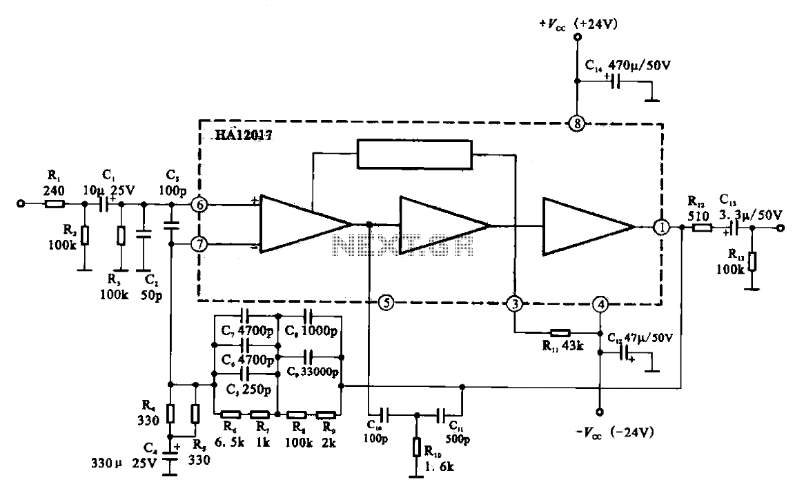
This circuit combines the advantages of low input offset voltage and drift without compromising the overall dynamic performance of the system. When compared to a standalone FET input operational amplifier, the composite amplifier circuit demonstrates a 20-fold improvement in...
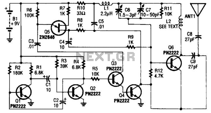
The transmitter utilizes a 6BW6 vacuum tube to achieve an output power of approximately 5 watts. The circuit includes a component CI that is calibrated to produce the cleanest continuous wave (CW) note. The tuning capacitors C8 and C9...
Warning: include(partials/cookie-banner.php): Failed to open stream: Permission denied in /var/www/html/nextgr/view-circuit.php on line 713
Warning: include(): Failed opening 'partials/cookie-banner.php' for inclusion (include_path='.:/usr/share/php') in /var/www/html/nextgr/view-circuit.php on line 713