
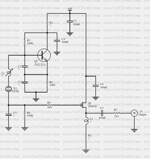
96Mhz crystal oscillator
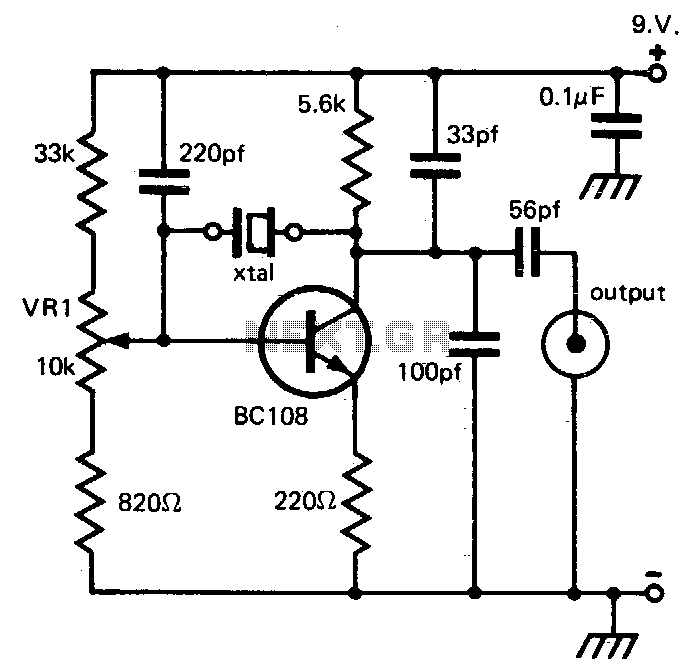
The described circuit is likely a simple oscillator designed to generate a periodic waveform with a peak-to-peak voltage of approximately one volt. The oscillation can be achieved through various methods such as using a relaxation oscillator, a Colpitts oscillator, or a simple RC oscillator configuration.
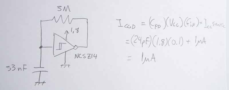
The power supply requirement is specified as nine volts, which suggests that the circuit may be powered by a standard battery or a regulated power supply. The low power consumption of around 1 mA indicates that the circuit is efficient, making it suitable for battery-operated devices or applications where power conservation is critical.
The output waveform can be utilized in various applications, including signal generation for testing purposes, clock signals for digital circuits, or as a modulation source in communication systems. The circuit's design should ensure stability and reliability in its oscillation performance, possibly incorporating feedback mechanisms to maintain consistent output characteristics.
In practical implementations, components such as resistors, capacitors, and transistors (or operational amplifiers) are typically used to define the oscillation frequency and shape of the output waveform. The choice of components and their values will significantly influence the performance of the circuit, including factors like frequency stability, output amplitude, and waveform distortion.
Overall, this circuit represents a fundamental building block in electronics, demonstrating the principles of oscillation and signal generation with a focus on low power consumption and manageable output levels.This circuit provides reliable oscillation and an output dose to one volt peak-to-peak Power consumption is around 1 mA from a nine volt supply. 🔗 External reference
Related Circuits
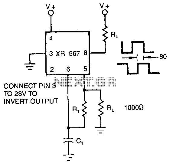
The XR-567 operates as a precision oscillator, providing two distinct square-wave outputs at pins 5 and 8, which are nearly in quadrature phase with one another. Due to the internal biasing configuration, the typical phase shift between the two...
A crystal oscillator circuit is a straightforward oscillator circuit that can be easily understood through its schematic diagram. It serves as a replacement for a conventional oscillator network, which typically consists of an LC combination. This simplicity is also...
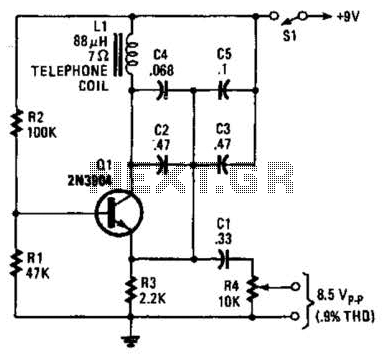
An 88 mH surplus telephone toroidal coil is utilized in a 1 kHz oscillator. It can provide up to 8 V peak-to-peak into a high-impedance load. The total harmonic distortion (THD) is 0.9%. The circuit employs an 88 mH toroidal...
The output of this circuit should be connected to a high-impedance load, typically greater than 100K ohms, while noting that the impedance of capacitor C4 is approximately 3K ohms. A PNP transistor may also be utilized, requiring adjustments to...
The power supply varies, and the circuit must operate at under 10 µA of current (excluding the capacitor charging). It triggers a Silicon Controlled Rectifier (SCR) every 10 to 30 seconds as long as the power supply is above...
This crystal oscillator is designed to operate with fundamental crystals with less than 1 mW dissipated in the crystal. The signal current is filtered by the crystal and develops a voltage across a capacitor with about 500 ohm of...
Warning: include(partials/cookie-banner.php): Failed to open stream: Permission denied in /var/www/html/nextgr/view-circuit.php on line 713
Warning: include(): Failed opening 'partials/cookie-banner.php' for inclusion (include_path='.:/usr/share/php') in /var/www/html/nextgr/view-circuit.php on line 713