
transistors Low power low voltage slow (0.1Hz) oscillator
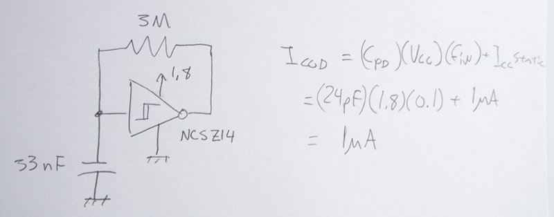
The circuit described is a low-power SCR triggering system designed to operate efficiently within a specified voltage range. The primary function of this circuit is to periodically trigger an SCR, which allows for controlled switching in various applications, such as in lighting or motor control systems.
The circuit operates by utilizing a timing mechanism that generates a pulse every 10 to 30 seconds, depending on the power supply voltage. A resistor-capacitor (RC) timing network can be employed to achieve the desired timing intervals. The capacitor is charged through a resistor, and once it reaches a threshold voltage, it can trigger the SCR. The design must ensure that the capacitor charging current does not exceed 10 µA, which necessitates careful selection of resistor values to extend the timing intervals at lower voltages.
In terms of voltage operation, the circuit is designed to function effectively at a minimum of 1.8 VDC and up to 7.0 VDC. This range allows for flexibility in power supply choices, accommodating both battery-operated and mains-powered applications. The design should incorporate components that can reliably operate within this voltage range without significant power loss.
Cost-effectiveness is a critical factor in the design process. The use of low-cost components such as resistors, capacitors, and the SCR itself is preferred over more expensive alternatives like microcontrollers. This approach not only reduces the overall cost of the circuit but also simplifies the design, making it easier to implement in various applications.
Overall, the circuit must be optimized for low power consumption, reliable operation across a specified voltage range, and cost efficiency, ensuring that it meets the requirements while remaining practical for real-world applications.The power supply varies, and the circuit must operate on under 10uA of current (not counting charging the cap). It triggers an SCR every 10-30 seconds as long as the power supply is above 1. 8VDC, and must operate across a range of 1. 8 and 7. 0 VDC. The timing isn`t critical - around 10-30 second intervals to trigger the SCR is fine (a short positiv
e pulse). The lower the voltage, the longer the time interval is fine. The kicker is the low current requirement (10uA or less), low voltage requirement (1. 8V) and, as always, low cost (ie, replacing a 10 cent PUT with a 30 cent microcontroller would not be ideal). 🔗 External reference
Related Circuits
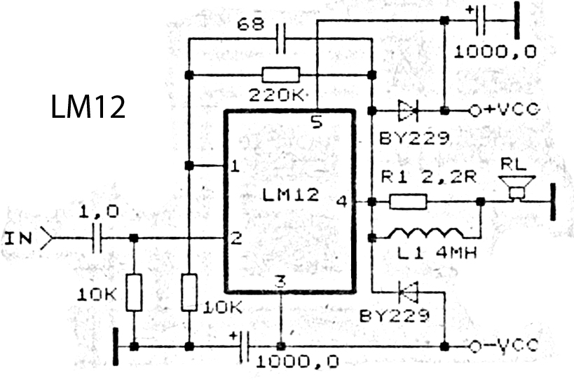
This is an amplifier circuit utilizing the LM12 integrated circuit as the primary amplifier. The amplifier delivers a power output of 150 watts and operates with a load impedance of 4 ohms. It is classified as a high-output power...

Cable and xDSL modems are increasingly popular, leading to a need for designs that interface with existing telephones at subscriber locations. The subscriber line interface circuit (SLIC) within the modem must ring the phone and provide loop current during...
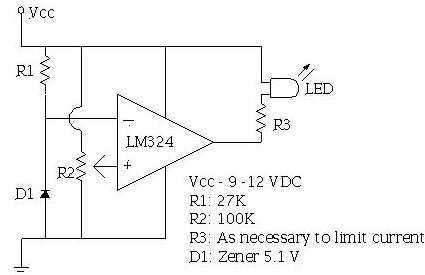
An ECU must have a way to monitor battery voltage. Here is a simple op-amp based circuit which will illuminate the LED when the battery voltage drops to a certain level. The turn-on point is set with R2. You...
Many applications do not require the precision of a digital or analog (bar graph) indicator but still benefit from more than a simple low/high signal. An example is a battery charge level indicator in a car. This basic circuit,...
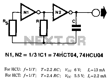
When frequency stability is not of primary importance, a simple yet reliable digital clock oscillator can be constructed using relatively few components. High-speed CMOS (HCU/HCf) inverters or gates with an inverter function are particularly suitable for creating such oscillators...
Mobile phone battery chargers available in local markets can be quite expensive. The circuit presented here offers a low-cost alternative for charging cellular phone batteries or battery packs with a rating of 7.2 volts. This low-cost phone battery charger circuit...
Warning: include(partials/cookie-banner.php): Failed to open stream: Permission denied in /var/www/html/nextgr/view-circuit.php on line 713
Warning: include(): Failed opening 'partials/cookie-banner.php' for inclusion (include_path='.:/usr/share/php') in /var/www/html/nextgr/view-circuit.php on line 713