
9V FM Radio Transmitter
The FM transmitter circuit described is designed to operate efficiently within the FM broadcast band, utilizing standard electronic components to achieve its functionality. The circuit is structured to provide a clear and stable transmission over the specified range, making it suitable for various applications, including hobbyist projects or educational demonstrations.
In the circuit, the BF494 transistor serves as the VHF oscillator, generating the radio frequency signal. The BF200 preamplifier amplifies the weak audio signal from the microphone before it is further processed. The 2N2219 transistor acts as a driver, boosting the signal strength before it reaches the power amplifier stage, which is built around the 2N3866 transistor. This stage is responsible for providing the necessary power to transmit the signal over a distance.
The use of a condenser microphone ensures that the audio input is captured with high fidelity, while the tuning capacitor allows for fine adjustments to the frequency, ensuring compliance with the desired transmission specifications. The inclusion of various capacitors helps filter and stabilize the circuit, contributing to improved performance and signal clarity.
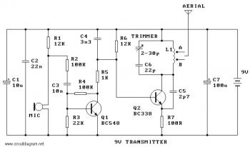
Overall, this FM transmitter circuit exemplifies a straightforward approach to creating a low-power broadcasting solution, suitable for experimentation and learning in the field of electronics. The component selection and circuit design facilitate ease of assembly, making it accessible for individuals with basic electronic skills.Here the simple and low cost FM transmitter circuit. The frequency range of this FM transmitter should be about 89MHz 109MHz. Output power is about 9mW at 9V. R1, R6_12K R2, R4_100K R3_22K R5_1K R7_100R Q1_BC338 Q2_BC548B Microphone JinIn ECM-60P B1 C1_10uF/25V C2_22n C3_10n C4_3n3 C5_2p7 C6_22p C7_100uF/16V tuning capacitor_0-30pF This is a low cost and easy build low powered FM transmitter. The range of the FM transmitter claimed about 300 feets when running at 9V supply. And the range claimed to be increased become about 400 feet when running it at 12V supply. Take a note that this transmitter should not be used as. This is the FM transmitter circuit which apply 4 radio frequency stages, that are a VHF oscillator designed around transistor BF494 (T1), a preamplifier designed around transistor BF200 (T2), a driver designed around transistor 2N2219 (T3) and also a power amplifier designed around transistor 2N3866 (T4). A condenser microphone is wired at the input of. The following diagram is the FM transmitter circuit with FM transmision up to 4W. Voltage supply for this circuit is 12-16V with current consumption of 100-400mA. This circuit works with frequency of emission range of 88-108MHz. Components List: R1, R2 = 10K Ohm (1/4 W) R3 = 47 Ohm (1/4 W) C1, C2 = 1nF. Easy FM tracking transmitter project :). The circuit designed by Tony van Roon, and here the FM tracking transmitter diagram: Components List: R1 = 10K C1 = 100uF/10V C2 = 10nF C3 = 4-40pF trimmer capacitor C4 = 4.
7pF IC1 = LM3909 Q1 = 2N3904 NPN transistor LED1 = Red LED/or another color as you. 🔗 External reference
Related Circuits
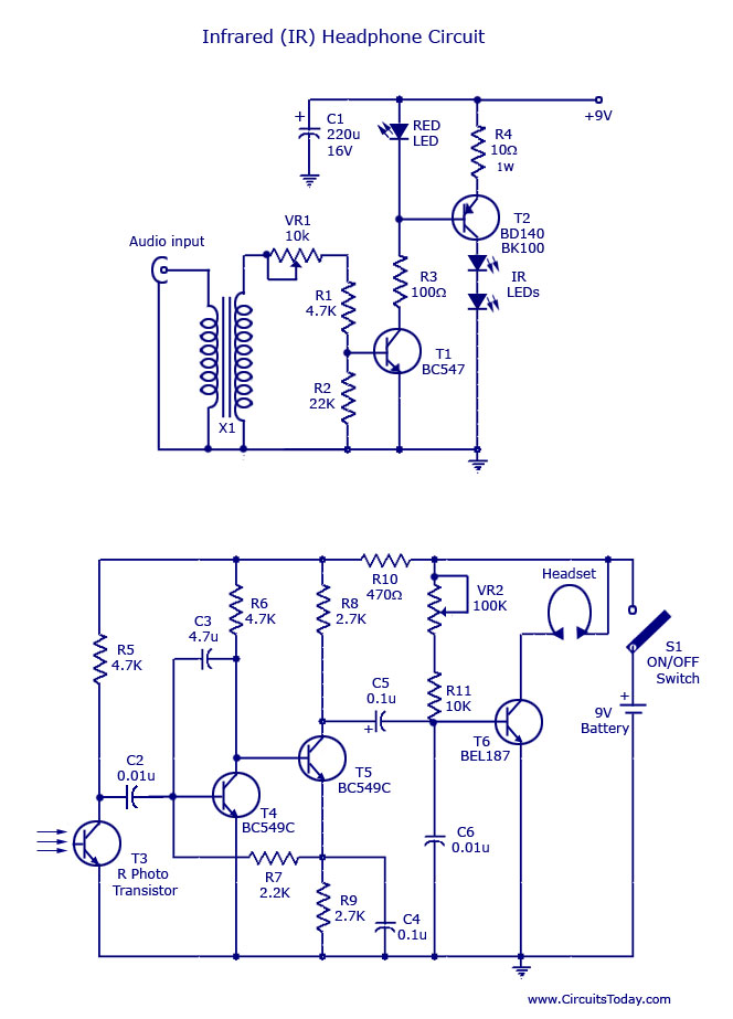
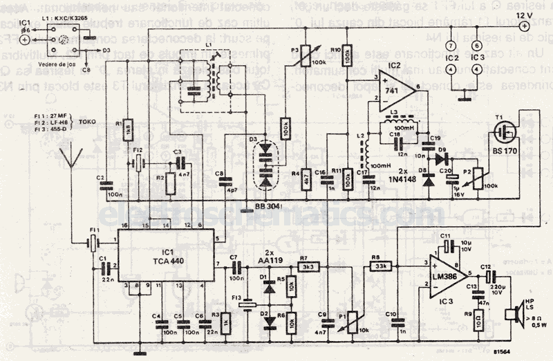
This document outlines a simple infrared (IR) headphone circuit designed for listening to television or radio without disturbing others. The IR headset is a preferable option for beginners compared to FM headsets due to its desirable sound quality that...
The receiver is a triple superheterodyne receiver with two phase-locked loop (PLL) guided local oscillators. The first local oscillator (LO) operates at 2.1 GHz and can be adjusted in increments of 500 kHz, down-converting the received signal to a...
A basic detector radio set that utilizes a vacuum tube instead of a crystal detector. This radio requires minimal components, and due to its inherent simplicity, it is easy to construct. Despite its simplicity, this receiver performs well when...
The RF design and construction of radio frequency oscillators. Radio frequency (RF) oscillators are essential components in various electronic systems, generating signals at specific frequencies used for communication, signal processing, and other applications. The design of RF oscillators involves several...
Narrow Band Frequency Modulation (NBFM) is utilized in this 27 MHz transmitter circuit schematic. This circuit is based on the Motorola MC2833 VHF transmitter, which integrates FM modulation and narrow band capabilities into a single chip. P1 is designated...
Wireless headphone transmitter and receiver systems are now widely available in the market, offering a variety of pricing options along with reliable technical specifications for various applications. These include wireless headphones for televisions, computers, and earbuds. A wireless headphone...