
Wireless Headphone Transmitter Receiver Circuit
The wireless headphone transmitter and receiver circuit operates effectively by utilizing amplitude modulation (AM) for audio transmission. The transmitter section incorporates an oscillator circuit that generates the carrier frequency, modulated by the audio signal input. This modulation is achieved through the preamplifier IC (741), which amplifies the audio signal before it is fed into the modulator. The output of the modulator is then transmitted through the ferrite rod antenna, which radiates the signal over the designated frequency range.
In the receiver section, the ZN415 IC plays a crucial role in demodulating the incoming signal. It extracts the audio signal from the received carrier wave, which is then amplified to drive the headphones. The low power requirement of 1.5V for the receiver makes it suitable for portable applications, ensuring extended usage without frequent battery changes. The trimmer capacitor (C1) allows for fine-tuning of the reception frequency, accommodating variations in the transmitter frequency and ensuring optimal signal clarity.
Overall, the design of the wireless headphone transmitter and receiver circuit emphasizes simplicity and efficiency, making it accessible for hobbyists and professionals alike. The choice of components, including inductors and transistors, is critical in achieving the desired performance characteristics, such as range and audio fidelity. Further enhancements can be made by exploring frequency modulation techniques, which could improve sound quality and reduce interference compared to traditional AM transmission.Wireless headphone transmitter receiver now widely available in the market with a variety of pricing options with a reliable technical specification for a variety of allocations which include wireless headphones for tv or tv headphones, wireless earbuds, wireless headphones for computers, or wireless headsets for computers. A wireless headphones i s nothing but a wireless headphone transmitter receiver. A wireless headphone transmitter receiver consists of a transmitter to function as the sender of the audio from the source and a receiver that receives voice which can then be heard through a headphone. The price of a wireless headphone range $ 20 - $ 400 with different shapes and different qualities. For a wireless headphone with the best quality, you can select a digital wireless headphones like Sennheiser RS 170, which has features Dynamic Bass and Surround Sound.
When faced with a decision to choose a best wireless headphones, I think you will not be settled on one if they do not limit it to basic uses of wireless headphones themselves. The development of wireless technology and audio is very fast, could be on a wireless headphone that features the perfect clarity of sound, such as noise canceling wireless headphones.
However, here we have yet to discuss this further just want to know the basic functions of a wireless headphone transmitter receiver circuit. As has already mentioned above that in a wireless headphone consisted of a transmitter and a receiver.
We do not speak the audio quality is generated in the receiver (headphone), just to give you a picture to the hobby of electronics to know fundamentally about the wireless headphone transmitter receiver. The quality of reception of the wireless headphone transmitter is approximately 2 meters. Oscillator frequency is in the AM band (SW1) is 1750 KHz-3500 kHz using ferrite rod antenna. Audio signal is received and amplified through a preamplifier IC 741 and the buffer by TC1 Transistor BD241.
Signal D1 serves as an oscillator voltage stabilizer which is a modulated audio transmitter which are AM (Amplitude Modulation). The supply voltage used between 12-18V with current consumption about 150mA. L1 is a toroidal core T50-2 with 80 turns, 0. 2mm G. L2 requires a 10-20cm ferrite rod. L2a has three turns, 0. 6mm G Coiled Ground at the end of L2b sandwiches has 30 turns, 0. 5mm G. This wireless headphone receiver built using IC ZN415 to short wave receivers manufactured by Ferranti.
Use of this IC is to ensure a quality reproduction that has an audio amplifier and the MA detector need only be supplied with a 1. 5V battery voltage with a current consumption of 5mA. To select the frequency of reception of the wireless headphone receiver, you need to adjust the trimmer C1 with a non-metal screw on the band SW1, with a frequency range of 1700 KHz-3400 KHz.
Component L1 has 40 turns, 0. 2 G G 20mm copper and ferrite. Where to obtain the audio quality and signal reception is clear. You can use the Frequency Modulation (FM) on the wireless headphones, so you need to modify the wireless headphone transmitter receiver circuit is. 🔗 External reference
Related Circuits
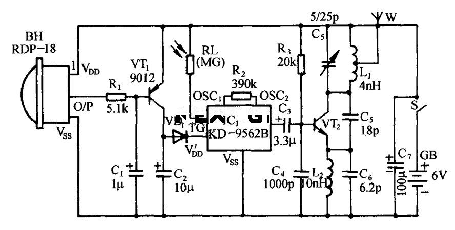
The circuit includes an infrared sensor head, electronic switches, an audible audio circuit, and an FM radio circuit. It is designed for installation in banks, treasuries, and other areas requiring supervision during evening hours in lieu of staff presence....
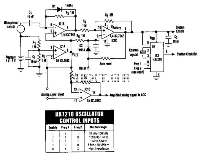
The HA7210 oscillator, in conjunction with the IOL7642 quad CMOS operational amplifier, forms a sleep-mode control circuit. This circuit can enter sleep mode when a logic high is applied to the Reset input or through an RC timer that...
This circuit measures the distance covered during a walk. The hardware is housed in a compact box that can be conveniently placed in a pants pocket. The display is designed as follows: the leftmost display, D2 (the most significant...
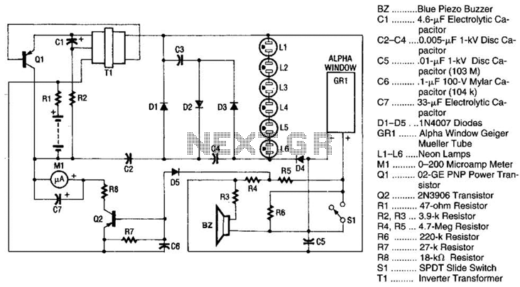
Q1 is a PNP power transistor used in conjunction with a ferrite transformer to form a blocking-type oscillator. This oscillator operates at a fixed frequency, with feedback for sustaining oscillations provided by capacitor C1. Due to the turns ratio...
This amplifier was born out of a need to use two sets headphones with my computer's sound-card. The design presented here is a 50mW power amplifier meant for phones with impedances of 32 Ohms and greater. I chose this...
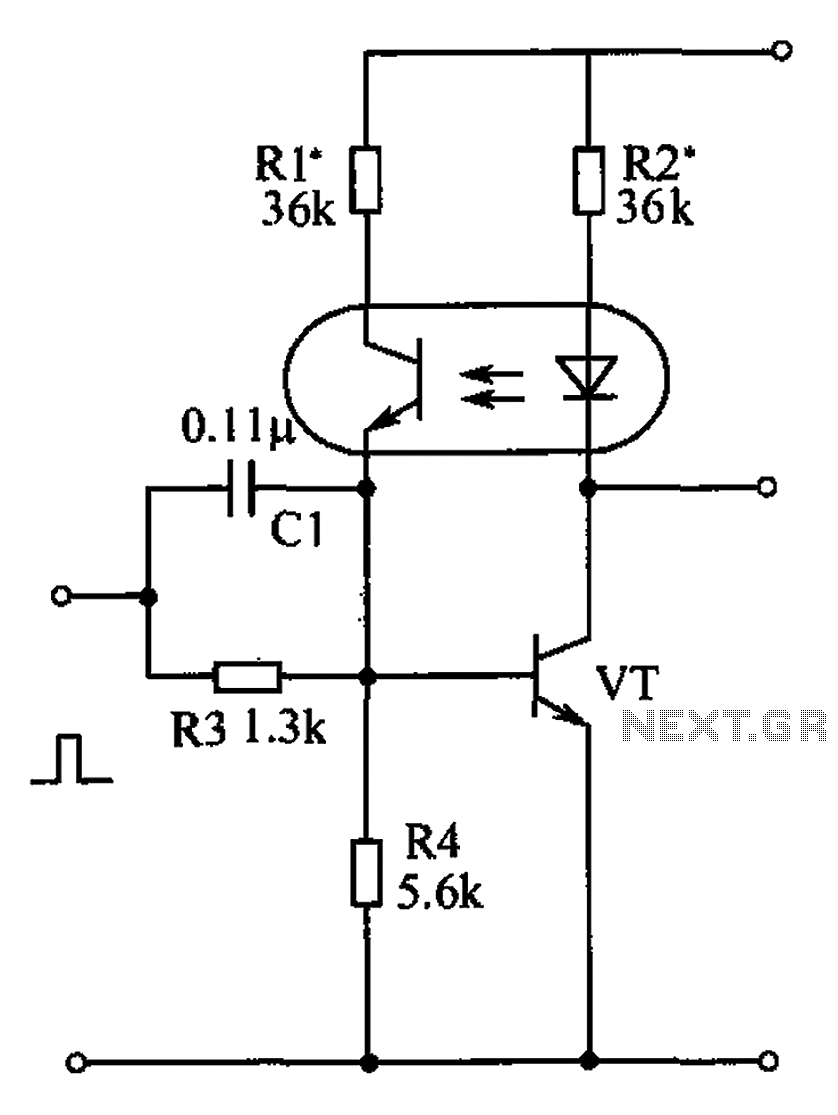
The bistable circuit and optocoupler transistor operate as illustrated in the accompanying figure. Initially, when the supply voltage is applied, the transistor VT is in the off state, resulting in a high output potential. Upon receiving a forward pulse...