
fm radio controller anti theft alarm
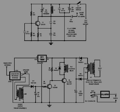
The FM radio-controlled anti-theft alarm circuit is designed for effective vehicle security by utilizing a compact transmitter-receiver setup. The transmitter, which operates within the VHF FM band, is strategically installed in the vehicle, ensuring that it remains concealed and functional during nighttime parking. The receiver, based on the CXA1019 IC, is tuned to the specific frequency emitted by the transmitter, creating a reliable communication link.
In normal operation, when the vehicle is stationary and the transmitter is powered, the receiver outputs a clean signal with no interference, allowing transistor T2 to remain in the off state. This configuration ensures that the relay driver transistor T3 does not activate, keeping the relay de-energized and the alarm system inactive.
The critical element of this system is its response to unauthorized movement. If an intruder attempts to drive the vehicle away, the distance between the transmitter and receiver increases, breaking the radio link. This disruption triggers the FM radio module to output a hissing noise, which is an indication of alarm activation. The generated hissing AC signals are coupled to the relay switching circuit through an audio transformer, effectively energizing the relay and triggering the alarm mechanism.
The relay, once energized, can be connected to various alarm systems, such as sirens or flashing lights, enhancing the overall security of the vehicle. The use of a 10k resistor (R5) ensures appropriate base biasing for transistor T3, allowing for reliable operation of the relay driver circuit.
Overall, this FM radio-controlled anti-theft alarm circuit offers a cost-effective and efficient solution for vehicle security, leveraging simple components to provide a robust defense against theft.This Circuit of FM radio-controlled anti- theft alarm can be used with any vehicle having 6- to 12-volt DC supply system. The mini VHF, FM transmitter is fitted in the vehicle at night when it is parked in the car porch or car park.
The receiver unit with CXA1019, a single IC-based FM radio module, which is freely available in the market at reason able rate, is kept inside. Receiver is tuned to the transmitter`s frequency. When the transmitter is on and the signals are being received by FM radio receiver, no hissing noise is available at the output of receiver. Thus transistor T2 (BC548) does not conduct. This results in the relay driver transistor T3 getting its forward base bias via 10k resistor R5 and the relay gets energised.
When an intruder tries to drive the car and takes it a few metres away from the car porch, the radio link between the car (transmitter) and alarm (receiver) is broken. As a result FM radio module gene-rates hissing noise. Hissing AC signals are coupled to relay switching circ- uit via audio transformer. 🔗 External reference
Related Circuits
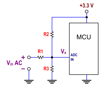
The ATtiny24 microcontroller's ADC is utilized to record an AC signal, which operates within a voltage range of 0 to 3.3V. A precision rectifier is employed to eliminate the negative portion of the signal. The circuit incorporates an LMC6484...
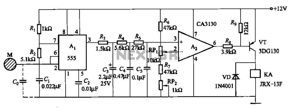
The circuit utilizes a 555 IC in conjunction with capacitors C1, C2, and a metal plate (tablet) M to create a distributed capacitance Co and resistor R1 connected to ground. Resistor R2 forms a self-excited multivibrator, while resistors R3...
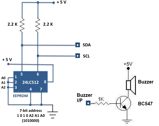
For beginners experiencing similar challenges, a general-purpose I/O board is recommended to minimize prototyping time and maximize space on the breadboard for projects. The construction of this board is straightforward. Basic I/O devices can be soldered onto a general-purpose...

This is a simple single-zone burglar alarm. The basic design includes automatic exit and entry delays. It does not include a siren cut-off timer, but with a small modification, one can be added to the circuit. The alarm will...
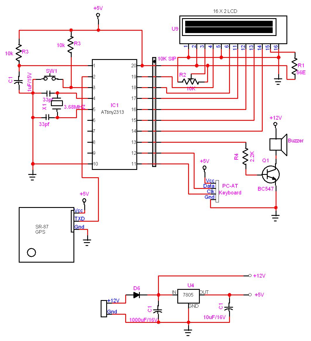
In this project, a GPS module is interfaced with an AVR microcontroller. The ATtiny2313 retrieves location data from the GPS and displays it on an LCD screen. The project involves the integration of a GPS module with the ATtiny2313 microcontroller,...

The wailing alarm circuit diagram includes the following component parts: R1 and R5 are 4.7 kΩ resistors, R2 is a 47 kΩ resistor, R3 is a 10 kΩ resistor, R4 is a 100 kΩ resistor, and Rx is specified...
Warning: include(partials/cookie-banner.php): Failed to open stream: Permission denied in /var/www/html/nextgr/view-circuit.php on line 713
Warning: include(): Failed opening 'partials/cookie-banner.php' for inclusion (include_path='.:/usr/share/php') in /var/www/html/nextgr/view-circuit.php on line 713