
Dummy Alarm Project
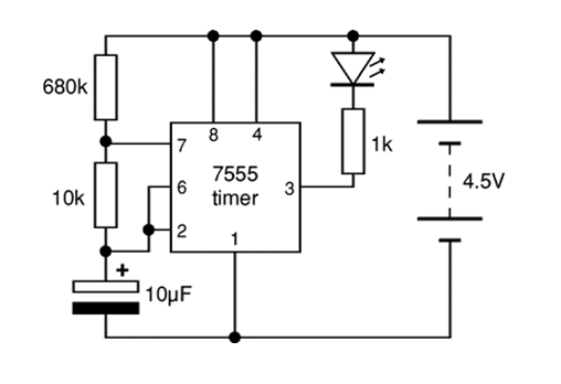
The 7555 timer IC is a versatile low-power component that operates similarly to the traditional 555 timer but is designed for applications requiring reduced power consumption. It is commonly used in various timing, pulse generation, and oscillator applications. The 7555 can be configured in astable, monostable, and bistable modes, allowing it to perform a wide range of functions, including generating precise time delays and producing square wave signals.
In the described application, a super bright red LED is employed as the output indicator. This choice is significant for applications where visibility is crucial, as the LED can emit a strong light while consuming minimal current, making it energy-efficient. The LED's brightness is a function of the current flowing through it, which is controlled by the output of the 7555 timer.
When configuring the 7555 in an astable mode, the timing components, typically resistors and capacitors, determine the frequency and duty cycle of the output signal. The output pin can drive the LED directly if the current requirement of the LED is within the output current rating of the 7555. If higher currents are needed, a transistor may be used to amplify the output signal, allowing for greater control over the LED brightness without exceeding the current limits of the timer IC.
The circuit design should include appropriate bypass capacitors near the power supply pins of the 7555 to ensure stable operation and reduce noise. Additionally, a current-limiting resistor must be included in series with the LED to prevent damage from excessive current.
Overall, the integration of the 7555 timer IC with a super bright red LED offers an effective solution for applications requiring low power consumption while still achieving high visibility output.The 7555 timer IC used is a low power version of the standard 555 timer. A ‘superbright red LED is used because this provides a bright flash with a low current. Th.. 🔗 External reference
Related Circuits
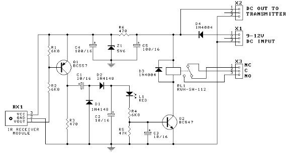
The TTY and the detector-transmitter unit are connected to separate phone jacks on the same line. When the ring sensor detects an incoming phone call, it activates the transmitter, which sends an RF signal to the receiver in the...
The circuit utilizes a 555 timer configured as an astable oscillator, powered by the emitter current of a BC109C transistor. In dry conditions, the transistor remains off due to the absence of bias current. However, when the probes come...
The primary components of this doorbell circuit include two NE555 timer integrated circuits (ICs). When the switch S1 is pressed momentarily, the loudspeaker emits a bell tone for the duration determined by the time period of the monostable multivibrator...

This is an infrared-based broken beam alarm designed to protect doors and entry passages. It emits a loud alarm when someone crosses the invisible infrared barrier. The infrared-based broken beam alarm system operates by utilizing a pair of infrared emitters...
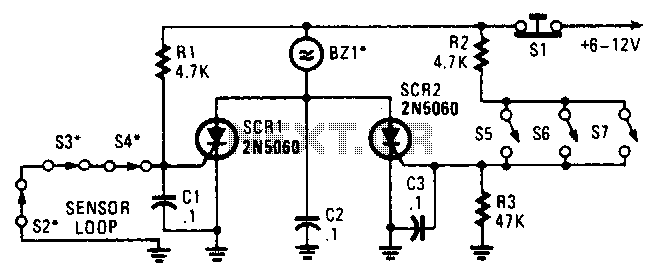
Two SCRs are utilized with two sensor loops. One loop employs series switches, while the other loop employs parallel switches. When a switch is actuated, the SCR is triggered. The alarm is designed to be a non-interrupting type. The circuit...
This door minder electronic project is based on a 555 timer circuit and utilizes an infrared (IR) beam to monitor doorways, passageways, or any other designated area. When the IR beam is interrupted, a relay is activated, which can...
Warning: include(partials/cookie-banner.php): Failed to open stream: Permission denied in /var/www/html/nextgr/view-circuit.php on line 713
Warning: include(): Failed opening 'partials/cookie-banner.php' for inclusion (include_path='.:/usr/share/php') in /var/www/html/nextgr/view-circuit.php on line 713