
a better sine wave

The operational amplifier circuit described operates effectively as an oscillator, utilizing a combination of RC low-pass filters to shape the output waveform. The configuration allows for a significant amplification factor, which is critical in achieving the desired output characteristics. The inclusion of three RC filters not only serves to filter out unwanted high-frequency components but also plays a pivotal role in phase manipulation, which is essential for sustaining oscillation. Each RC stage introduces a phase shift that is cumulative, ensuring that the feedback mechanism aligns correctly to maintain stable oscillation.
The choice of capacitors and resistors is crucial; using larger capacitors such as 0.1 µF allows for lower frequency oscillation, which is suitable for audio applications. The resistor values are also carefully selected to maintain the necessary gain while ensuring that the circuit remains stable and does not introduce excessive loading on the output. The gain adjustment via RF and RG is a common practice in op-amp circuits, allowing for fine-tuning of the output characteristics based on the specific application requirements.
The negative feedback mechanism employed in this circuit is a foundational principle in analog electronics, promoting stability and precision in the output signal. By delaying the feedback through the RC network, the circuit can effectively control the oscillation, preventing runaway conditions that could lead to distortion or instability. The observed startup ramp and stabilization indicate a well-designed circuit that efficiently transitions to its steady-state operation.
Overall, this op-amp oscillator circuit exemplifies the practical application of feedback and filtering in generating a clean sine wave output, suitable for various electronic applications, including signal generation and audio processing. The ability to modify the output level with additional amplification stages further enhances its versatility, making it a valuable component in analog circuit design.This one is actually a bit simpler to explain: the op-amp is set up with 25. 50x amplification, i. e almost a comparator (with 50x amplification, a 50 mV input above or below the 2. 5V will drive the output to its limit). And indeed, the output signal of the op-amp looks somewhat like a heavily clipped sine wave: The 3 resistors and 3 capacitors crea te 3 RC low-pass filters in series, removing all the higher frequencies, i. e. harmonics. A fairly clean sine wave comes out at the end, as you can see here: The frequency is determined by phase shifts . Each RC filter changes the phase of its input signal, and it will be by 60 ° at a certain frequency, so that 3 of them in series will then shift it by 180 °.
Since the signal is fed back to the - pin of the op-amp, that`s exactly the proper signal to generate the opposite output, i. e. shifted 180 ° out of 360 °. This analog stuff gets complicated don`t worry too much about it: just pick R and C values to get the right frequency, and make all of them the same.
I used 0. 1 µF caps i. s. o. 10 nF caps, i. e. 10x larger than the original circuit. With these values, the oscillation in my setup turned out to occur at just about 440 Hz, i. e. a pure musical A tone! I did have to increase the gain (1. 5 M © / 55. 2 k © = 27 in the above setup) to force oscillation. I changed RF to 1 M © and RG to 22 k ©, for a gain of 47. This RG value is a bit low, it loads down the last RC section quite a bit. What you`re seeing here is a classical example of a negative feedback loop, which ends up in a very stable state of oscillation. It oscillates because we`re delaying the feedback signal by about 2. 27 ms through the RC chain. So the op-amp constantly overshoots around its mid-point (the 2. 5V applied to the + input), but does so in a very controlled way. The amplitude can`t increase any further, since the op-amp is clipping at its limits already, and the amplification factor is large enough to keep boosting the swing up to that limit.
You can see the startup ramp and stabilization when powering up: A clean signal compared to the previous experiment. The 2nd harmonic is ‰ 42 dB below the fundamental wave, the rest is even lower. Using this calculator, we can see that this represents about 0. 8% harmonic distortion. Glad you got a working sinewave circuit! It seems easy enough to use another opamp stage to get whatever level output you need, I assume you`ll be using a separate driver anyway if you need significant current.
🔗 External reference
Related Circuits
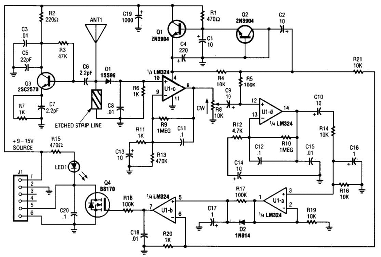
Operating at approximately 1.1 GHz, the detector senses disturbances in the electromagnetic field surrounding the antenna. The Doppler signal generated by detector D1 is amplified and used to control a power MOSFET switch. The antenna consists of a short...
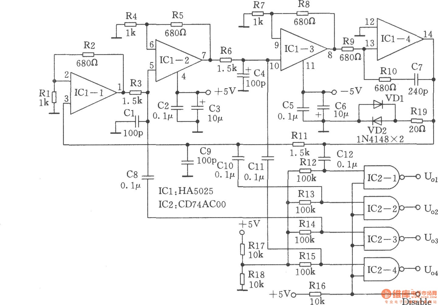
Many RC oscillators utilize an advanced circuit in the phase shift unit. This configuration employs a voltage feedback amplifier, which experiences a significant decline in gain at higher frequencies, leading to the cessation of oscillation before achieving the desired...
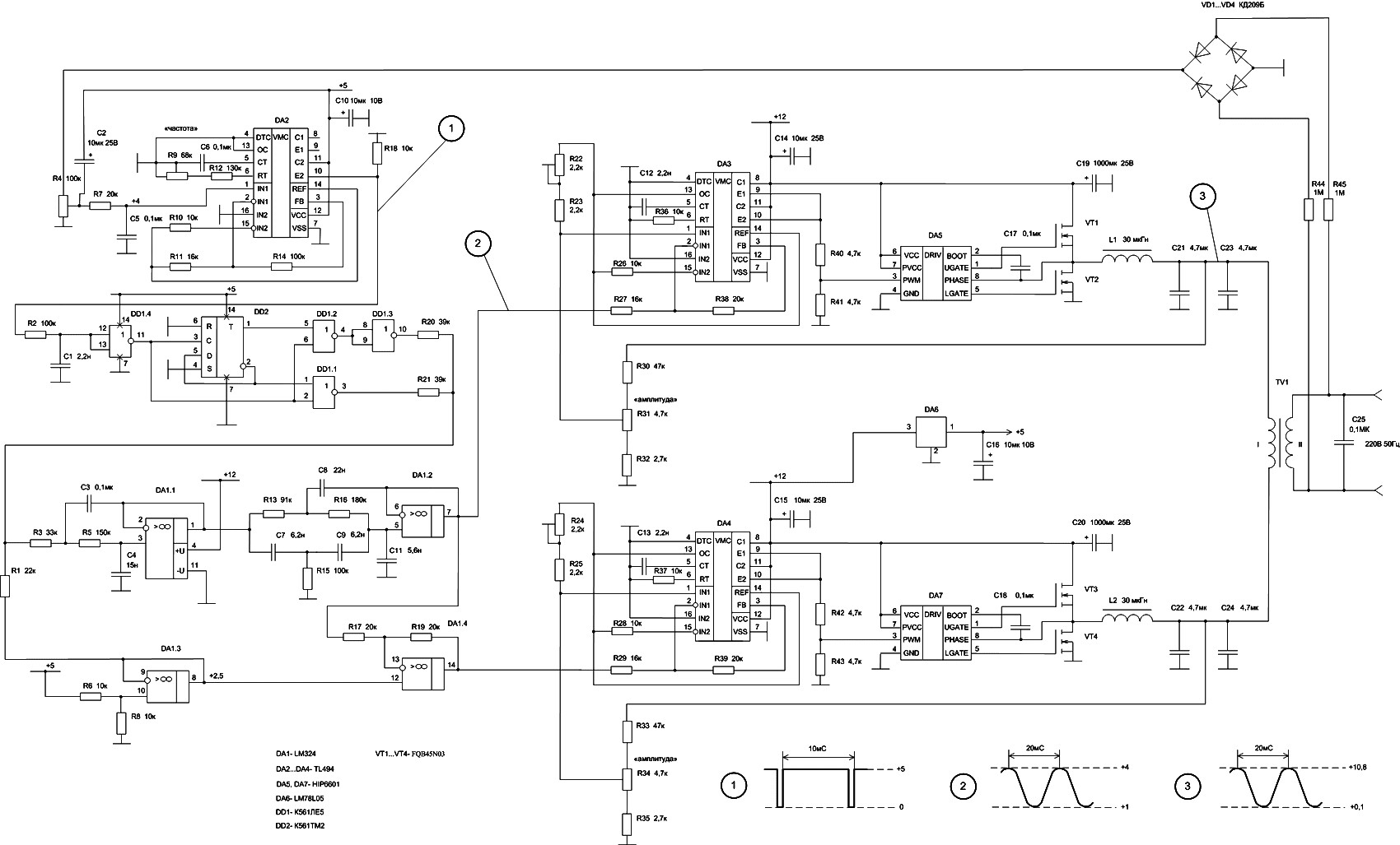
The 50W inverter circuit is built using the power MOSFET FQB45N03 and the IC TL494. This inverter converts a 12-14V DC input from a car battery into a 220V AC output with a 50Hz sine wave frequency. The main...
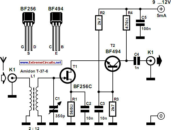
The circuit presented illustrates that despite the availability of various new components and technologies, it remains feasible to design useful and interesting circuits. The circuit utilizes two well-established transistors, the BF256C and the BF494. Along with the necessary resistors...
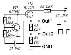
Square wave generators are typically based on symmetrical multivibrators using bipolar transistors of the same structure, along with two frequency-determining networks. However, a simpler oscillator can be constructed with two transistors of different structures (refer to figure 1) utilizing...
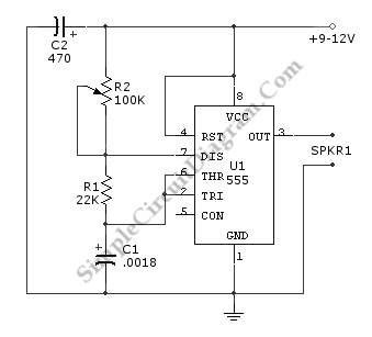
An ultrasonic sound wave can be generated using an electronic circuit. This simple electronic circuit can produce an ultrasonic wave with a frequency range of 12 kHz to... An ultrasonic sound wave generator circuit typically employs a few key components...