
active short wave antenna

The antenna amplifier circuit employs a direct coupling configuration, which enhances the frequency response and minimizes the signal distortion typically associated with capacitive coupling. The BF256C, a JFET transistor, is utilized as the input stage due to its high input impedance, which is critical for minimizing loading effects on the antenna. This transistor effectively amplifies the weak radio frequency signals received from the antenna.
The second transistor, BF494, is configured in a common-ground arrangement, which is a popular choice for RF amplification due to its stability and ease of integration with other circuit components. This configuration allows for a higher level of gain while maintaining a consistent output impedance, which is essential for driving subsequent stages or loads without signal degradation.
Resistors in the circuit are selected to set the biasing conditions for both transistors, ensuring they operate within their optimal regions. Capacitors are strategically placed to filter out unwanted noise and stabilize the power supply, further enhancing the amplifier's performance. The overall design is capable of operating effectively across the specified frequency range, making it suitable for various short-wave applications, including amateur radio and signal reception.
The gain of 20 dB indicates that the amplifier can significantly enhance weak signals, making it an effective solution for improving the overall performance of short-wave radio systems. This circuit exemplifies how traditional components can still be effectively utilized to create modern, high-performance electronic devices.The circuit presented here illustrates the fact that in spite of all kinds of new component and technology, it is still possible to design useful, and interesting, circuits. The circuit is based on two well-established transistors, a Type BF256C and a BF494. In conjunction with the requisite resistors and capacitors, these form a well-working ante nna amplifier. Note that they are direct coupled. Transistor T1 is the input amplifier cum buffer, while the BF494, in a common-ground configuration, provides the necessary amplification. The amplifier is designed for operation at frequencies between 10 MHz and 30 MHz, which is the larger part of the short-wave range, and has a gain of 20 dB.
🔗 External reference
Related Circuits
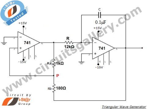
An operational amplifier-based triangular waveform generator is a simple circuit that is widely used in function generators. This circuit utilizes the 741 operational amplifier to create a triangular wave generator. The output waveform of an integrator will be triangular...
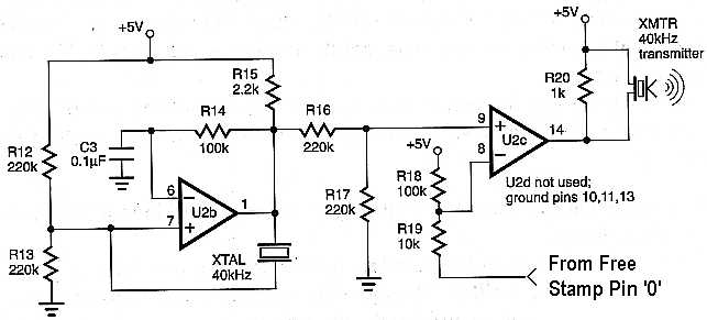
This project is ideal for use as a sensor in a robotic application. The circuit enables distance measurement from an object, with a measurement range of approximately 10 inches. An ultrasonic transmitter and receiver pair, tuned to 40 kHz,...
The total gain of the car antenna amplifier is approximately 30 dB, with an input impedance of around 10 kΩ at 30 MHz. The amplifier should be mounted directly at the base of the antenna to prevent signal losses...
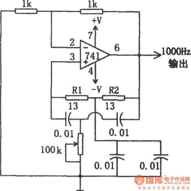
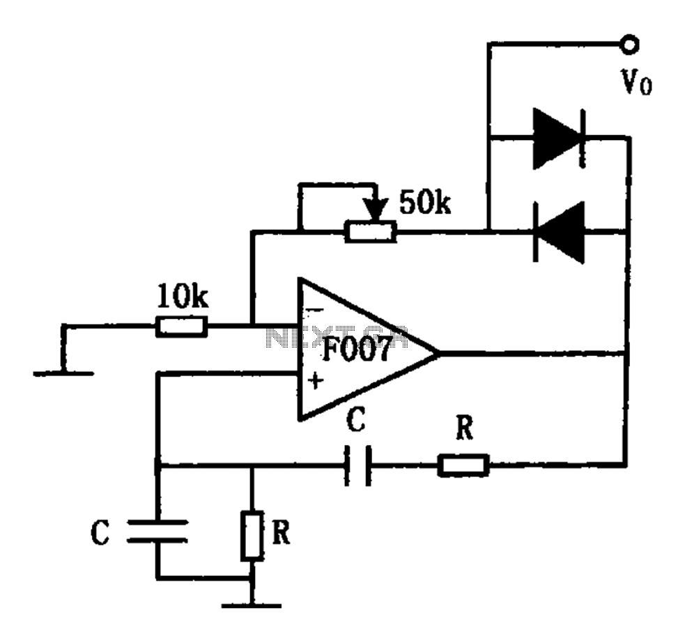
The circuit illustrated in the diagram is a 1 kHz sine wave oscillator circuit. Based on a double-T circuit configuration, it utilizes a standard 741 operational amplifier to generate a 1000 Hz sine wave output. The circuit begins oscillation...
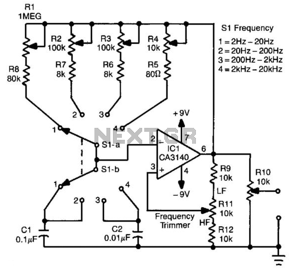
This circuit generates a square wave with a frequency range of 2 Hz to 20 kHz. It employs an operational amplifier in a relaxation oscillator configuration. The output voltage is approximately 15 V peak-to-peak. Resistors R1 through R4 serve...
The stable sine wave oscillator circuit is designed to maintain consistent oscillation. The loop gain must be carefully managed; if the gain is excessive, waveform distortion occurs, while insufficient gain can lead to cessation of oscillation. This circuit employs...