
12VDC to 220VAC Inverter with Sine Wave Output
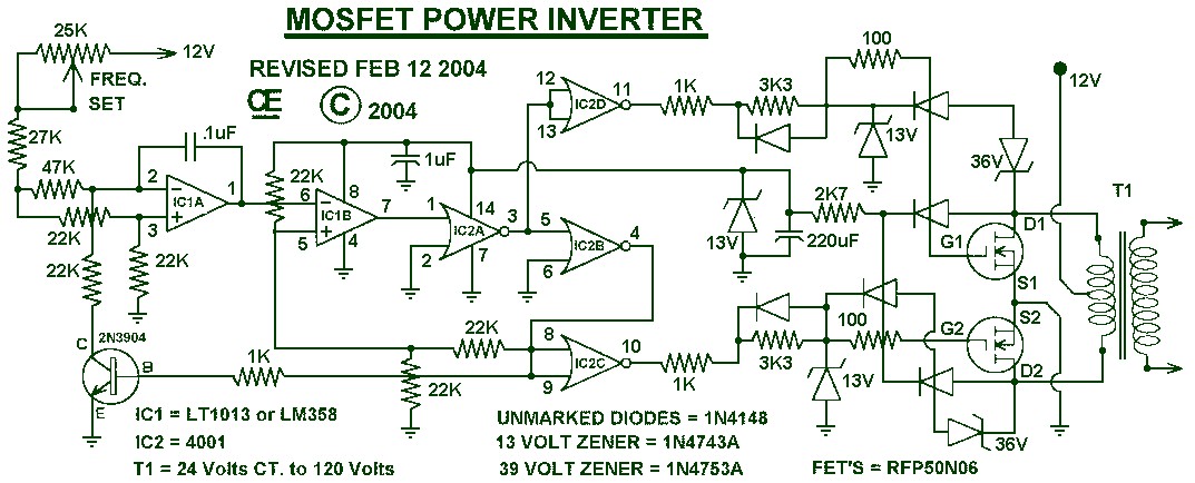
The inverter circuit described operates by utilizing a combination of power MOSFETs and control ICs to effectively convert DC voltage into AC voltage. The FQB45N03 MOSFET is known for its high efficiency and fast switching capabilities, making it suitable for inverter applications. The TL494 IC serves as the heart of the control system, providing necessary feedback and regulation to maintain stable output voltage and frequency.
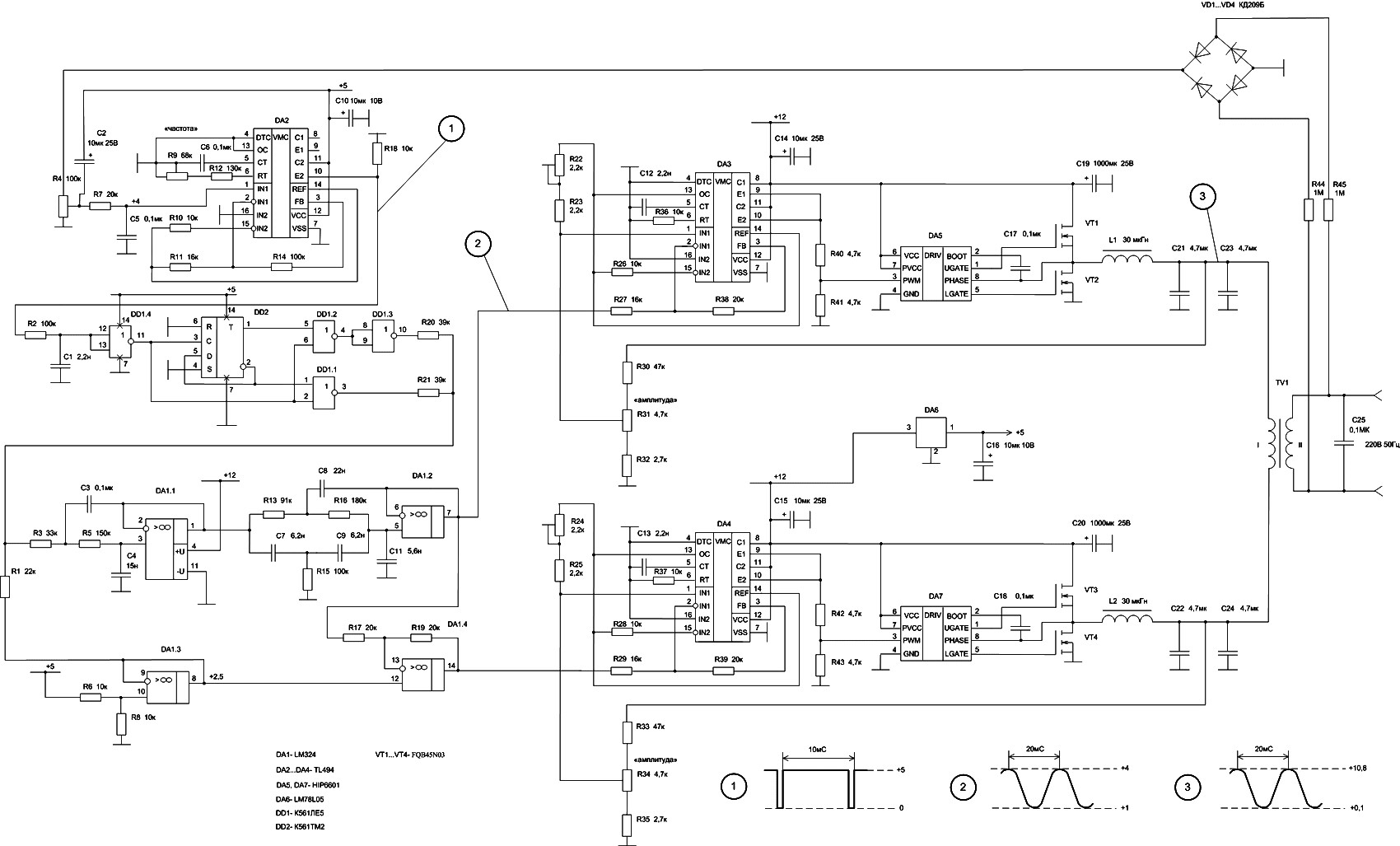
In the design, the DA2 section integrates the oscillator, voltage reference, and comparator functions to ensure precise control over the output waveform. The external components DD1 and DD2 are crucial for replicating the internal circuit behavior, enhancing the overall performance of the inverter.
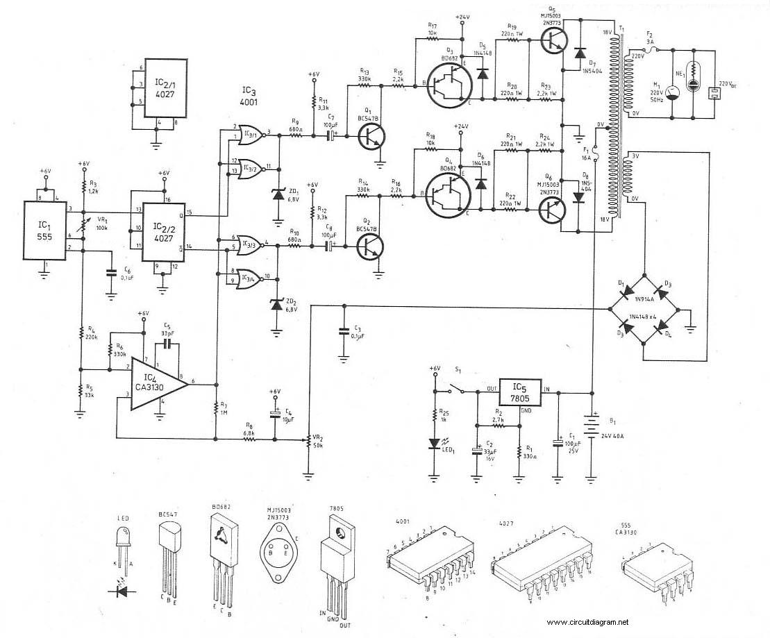
The use of two STP55NF06L MOSFETs allows the inverter to handle significant power loads, up to 500W, making it capable of powering various devices. The inclusion of the PIC16F628A microcontroller adds programmability, allowing for customized control over the inverter's operation.
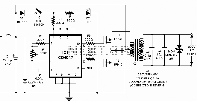
The schematic for the 100W inverter circuit highlights the use of the CD4047 IC, which is well-regarded for generating stable sine wave signals. The 2N3055 power transistor amplifies this signal to a level suitable for driving loads. This design is particularly beneficial for users needing a reliable power source for electronic devices in remote locations.
The Tripp Lite portable inverter exemplifies practical applications of such circuits, providing a versatile solution for converting vehicle battery power to AC power for personal electronics. Its compact design and minimal component count make it an attractive option for users on the go. The use of IRFZ44 MOSFETs in the design allows for efficient switching, ensuring that the inverter operates smoothly while delivering the necessary power output.
Overall, these inverter designs represent a blend of efficiency, simplicity, and versatility, catering to a wide range of applications in mobile power solutions.Here the 50W inverter circuit build based power MOSFET FQB45N03 and IC TL494. This inverter will convert 12-14V DC input from car battery, become 220V AC output with 50Hz sine wave frequency. The main oscillator, a voltage reference and comparator collected on DA2. External elements DD1 and DD2 repeated internal. This Modified Sine Wave Inverter frequency rate is 50Hz, give you 240V AC output. Powered by the 2 pieces of power MOSFETs STP55NF06L, the inverter capable to deliver up to 500W power. The PIC16F628A is programmed to produce a logic 5v signal for 5ms at pin 17 then 15ms off. . Here the schematic diagram of 100W Inverter Circuit which will convert 12VDC input to be 220VAC output.
The circuit built based IC CD4047 to generate sine wave signal 50Hz and then the power transistor 2N3055 will boost the signal so that the signal have high power (high electric current). Then. This is the 150W Tripp Lite portable inverter and it will convert the 12VDC input from car battery power source to become 120VAC output.
The inverter taps the power of your vehicle`s battery to power your personal electronics ”wherever life takes you. It`s the ideal power solution for mobile professionals, travelers. This DC to AC converter is very simple and contains no more than 12 components. IC CD4047 generates a signal with frequency 50/60Hz, who paraphase exits 10 and 11 is fed to the gates of MOSFET transistors IRFZ44.
Transistors alternately commute primary winding of the transformer floor, and appears on. We aim to transmit more information by carrying articles. Please send us an E-mail to wanghuali@hqew. net within 15 days if we are involved in the problems of article content, copyright or other problems. We will delete it soon. 🔗 External reference
Related Circuits
1000W Power Inverter circuit diagram: This is a power inverter circuit based on the MOSFET RFP50N06. The inverter is capable of handling loads up to 1000W, depending on the specifications of the transformer used. The RFP50N06 MOSFETs are rated...
This is the schematic diagram of a 300W power inverter circuit. The inverter utilizes the MJ15003 power transistor for final amplification. If the MJ15003 transistor is difficult to source, it can be replaced with a 2N3773. The inverter is...
Our programmable MP3 player has an interface to an LCD with a HD44780 controller. These are alphanumeric LCDs with one to 4 lines of text and 16 to 40 characters per line. However, these LCDs (and LCDs in general)...
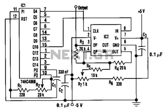
In this circuit, a square wave is filtered using a high-order low-pass filter designed to eliminate most harmonics of the waveform at a -3 dB frequency. Consequently, the output of the filter is a fundamental sine wave. This technique...
This single integrated circuit (IC) design is based on the Wien Bridge Oscillator, generating low distortion sine waves within a frequency range of 15 Hz to 22 kHz across two output voltage levels: approximately 0-250 mV and 0-2.5 Vrms....
This is a 100-watt inverter circuit diagram. It is built using the IC CD4047 and the MOSFET IRF540. This inverter has the capability to supply electronic devices that require 220VAC, with a maximum output of 100 watts from a...